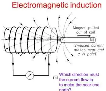
Wireless Electricity
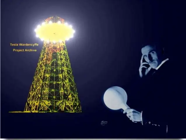

Wireless Electricity

Wireless electricity transmits power without wires using electromagnetic fields, such as magnetic resonance or microwave transmission. It enables charging devices remotely, powering sensors, and improving efficiency in smart grids, EVs, and wireless charging systems.


What is Wireless Electricity?

Wireless electricity refers to the transmission of electrical energy without physical conductors like wires.

✅ Powers devices through electromagnetic fields, like inductive coupling

✅ Enables contactless charging in consumer electronics and EVs

✅ Supports smart grids, IoT, and remote sensors with flexible energy delivery

Wireless electricity, also known as wireless power transmission, was first conceptualized by Nikola Tesla, a pioneer in the field of alternating current (AC) electricity. Tesla’s groundbreaking experiments at Colorado Springs in 1899 showcased how power could be transmitted without wires using a magnetic field. He used a Tesla coil to transmit 100 million volts of high power over a distance of 26 miles, wirelessly powering 200 light bulbs and an electric motor. His vision was to develop a wireless system capable of transmitting power over long distances with minimal energy loss.
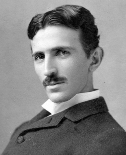
Tesla’s system relied on a high-frequency alternating current and magnetic resonance to transmit power wirelessly. His experiments with the Tesla coil laid the groundwork for modern wireless technologies, including short-range wi

reless power transmission systems, such as wireless charging pads and Wi-Fi routers. Wireless charging pads today utilize magnetic fields to transmit power to devices, a concept similar to Tesla’s idea of harnessing the Earth’s resonance to transmit power over longer distances. Tesla’s vision extended beyond short-range wireless systems—he dreamed of a global system where energy flows freely through the air without requiring a direct line of sight.

Tesla’s experiments also demonstrated the efficiency of wireless systems. The Tesla coil could transmit power wirelessly to fluorescent light bulbs even when they were several feet away from the coil. This concept of powering devices wirelessly has evolved over time, with companies like Wi-Charge developing systems to transmit power wirelessly to small devices. In Tesla’s time, he envisioned a world where any amount of power could be transmitted wirelessly across the globe. However, financial struggles eventually led to the abandonment of his wireless power transmission projects, including the unfinished Wardenclyffe tower on Long Island. Devices powered wirelessly still rely on efficient energy flow, making concepts such as electrical resistance and impedance crucial to design and performance.

Despite Tesla’s challenges, modern advancements have kept his vision alive. Short-range wireless power transmission systems, like those used in Wi-Fi routers and wireless charging pads, are now commonplace. These technologies utilize magnetic fields to transmit power wirelessly over short distances, offering a practical solution for wirelessly charging devices such as smartphones and laptops. Wi-Charge is exploring the potential of wirelessly charging devices without requiring close contact, enabling more flexible and efficient energy distribution. Tesla’s coil and modern systems like Wi-Charge operate based on resonant principles, closely related to inductance and capacitance.


Modern Innovations in Wireless Electricity

Recent breakthroughs have brought Tesla’s dream closer to reality:

  • In 2024, DARPA successfully transmitted 800 watts of power over 5 miles using a laser beam—enough to make popcorn at the receiver site.

  • KAIST in South Korea demonstrated the ability to charge 40 smartphones at once using magnetic resonance over a distance of 5 meters.

  • Detroit’s Corktown district now hosts a functioning inductive charging roadway, allowing EVs to charge wirelessly while in motion.

These examples show that wireless electricity is no longer a distant vision but a rapidly advancing technology with real-world applications. Concepts such as watts, volts, and amperes remain fundamental even in advanced wireless systems.


Types of Wireless Power Transmission Technologies

Technology Type Description and Use Cases
Inductive Coupling Short-range charging pads for phones, laptops, and wearables
Magnetic Resonance Mid-range charging for larger devices and multiple receivers simultaneously
Microwave Transmission Long-range point-to-point energy transfer; used in research and satellites
Laser Power Beaming High-efficiency focused beams for distant targets; demonstrated by DARPA
Infrared Light (Wi-Charge) Contactless charging for smart locks and IoT devices


Applications of Wireless Electricity

  • Consumer Electronics: Wireless charging pads and smart home devices are now common.

  • Electric Vehicles (EVs): Inductive charging roads and parking pads reduce dependency on cable stations.

  • Medical Implants: Enables powering of implants and biosensors without invasive wiring.

  • Remote Sensors: In agriculture, factories, and infrastructure, wireless power extends sensor life.

  • Smart Grids: Flexible energy distribution for remote locations and emergency response.


Challenges and Future Outlook

Despite its promise, wireless electricity faces challenges:

  • Efficiency drops over distance

  • Alignment issues in inductive systems

  • Line-of-sight limitations in laser and IR systems

  • Safety regulations for high-power beaming

However, the future is promising. Emerging materials, such as metamaterials and metasurfaces, are enhancing transmission efficiency. AI-enhanced beam control, dynamic alignment systems, and frequency-agnostic receivers are under development.

From Tesla's early experiments to DARPA's record-setting laser transmission, wireless electricity is evolving into a transformative force. As the technology matures, its applications will expand, powering a world that may one day be truly wire-free.


Related Articles


Related News

Capacitance Explained

Capacitance: Understanding the Ability to Store Electricity

Capacitance is an essential concept in electrical circuits, and it describes the ability of a capacitor to store electrical energy. Capacitors are electronic components used in many circuits to perform various functions, such as filtering, timing, and power conversion. Capacitance is a measure of a capacitor's ability to store electrical energy, and it plays a crucial role in the design and operation of electrical circuits. This article provides an overview of capacitance, including its definition, SI unit, and the difference between capacitor and capacitance.


What is Capacitance?

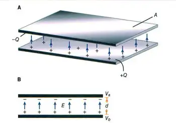
Capacitance is the ability of a capacitor to store electrical charge. A capacitor consists of two conductive plates separated by a dielectric material. The conductive plates are connected to an electrical circuit, and the dielectric material is placed between them to prevent direct contact. When a voltage source is applied to the plates, electrical charge builds up on the surface of the plates. The amount of charge that a capacitor can store is determined by its capacitance, which depends on the size and distance between the plates, as well as the dielectric constant of the material.

The energy storing capability of a capacitor is based on its capacitance. This means that a capacitor with a higher capacitance can store more energy than a capacitor with a lower capacitance. The energy stored in a capacitor is given by the formula:

Energy (Joules) = 0.5 x Capacitance (Farads) x Voltage^2

The ability to store energy is essential for many applications, including filtering, timing, and power conversion. Capacitors are commonly used in DC circuits to smooth out voltage fluctuations and prevent noise. They are also used in AC circuits to filter out high-frequency signals.


What is Capacitance and the SI Unit of Capacitance?

Capacitance is defined as the ratio of the electrical charge stored on a capacitor to the voltage applied to it. The SI unit of capacitance is the Farad (F), which is defined as the amount of capacitance that stores one coulomb of electrical charge when a voltage of one volt is applied. One Farad is a relatively large unit of capacitance, and most capacitors have values that are much smaller. Therefore, capacitors are often measured in microfarads (µF) or picofarads (pF).

The capacitance of a capacitor depends on several factors, including the distance between the plates, the surface area of the plates, and the dielectric constant of the material between the plates. The dielectric constant is a measure of the ability of the material to store electrical energy, and it affects the capacitance of the capacitor. The higher the dielectric constant of the material, the higher the capacitance of the capacitor.


What is the Difference Between Capacitor and Capacitance?

Capacitor and capacitance are related concepts but are not the same thing. Capacitance is the ability of a capacitor to store electrical energy, while a capacitor is an electronic component that stores electrical charge. A capacitor consists of two conductive plates separated by a dielectric material, and it is designed to store electrical charge. Capacitance is a property of a capacitor, and it determines the amount of electrical charge that the capacitor can store. Capacitance is measured in Farads, while the capacitor is measured in units of capacitance, such as microfarads (µF) or picofarads (pF).


What is an Example of Capacitance?

One example of capacitance is a common electronic component known as an electrolytic capacitor. These capacitors are used in a wide range of electronic circuits to store electrical energy, filter out noise, and regulate voltage. They consist of two conductive plates separated by a dielectric material, which is usually an electrolyte. The electrolyte allows for a high capacitance, which means that these capacitors can store a large amount of electrical energy.

Another example of capacitance is the human body. Although the capacitance of the human body is relatively small, it can still store a significant amount of electrical charge. This is why people can sometimes feel a shock when they touch a grounded object, such as a metal doorknob or a handrail. The capacitance of the human body is affected by several factors, including the size and shape of the body, as well as the material and proximity of the objects it comes into contact with.

View more

3 PHASE ELECTRICITY

3 Phase Electricity supplies AC three-phase power via 120° phase-shifted sinusoidal waveforms, enabling balanced loads, higher power factor, efficient distribution, and smooth torque for industrial motors across commercial facilities and the electrical grid.


What Is 3 Phase Electricity?

An AC system with three sinusoidal phases delivering balanced, efficient power for distribution and industrial motors.

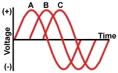
✅ Three 120° phase-shifted AC waveforms share balanced loads.

✅ Lower conductor size and losses than single-phase systems.

✅ Powers large motors with smoother torque and better efficiency.


3 phase electricity is referred to alternating current. It is best described as the timing of the electron movements. It is the most common delivery method worldwide because it is a cheaper and easier way to transmit power from one place to another. While this method of electrical transmission is popular in industrial, commercial and institutional power systems, most homes only use single-phase power. For a concise overview, see the three-phase electricity guide for context.


What does it mean?

If wires are in "phase", it means that timing of the electron movement, back and forth, is the same. The electrons are "in step" or "in time".

For newcomers, the basic electricity tutorial explains charge, current, and phase in simple terms.

To transmit and distribute alternating current, it is more efficient to use 3 circuits that are out of sequence. This idea was discovered by Nikola Tesla (1856 -1943). Much of its efficiency is because there is always voltage (electrons moving) in at least one wire.

You can review how alternating current behaves in circuits in the how electricity works resource to see why shifting phases improves continuity.

He found that it is an arrangement that fits in very nicely with generator design. The 120° phasing separation allows close to the optimum spacing and size of the copper conductors around the stator bore. The compatible generator is the cheapest form to make. Design notes for 3-phase power highlight how 120° spacing reduces copper and iron losses.

This type of power is designed especially for large electrical loads where the total electrical load is divided among the three separate phasing sequences. As a result, the wire and transformers will be less expensive than if these large loads were carried on a single system.

Generators usually have three separate windings, each producing its own separate single-phase voltage. Since these windings are staggered around the generator circumference, each of the voltages is "out of phase" with one another. That is, each of the three reaches the maximum and minimum points in the AC cycle at different times.

Definitions of "phase angle" and "phase sequence" are covered in the electricity terms glossary for reference.

Power is generated at electric utilities in this way. But, if this power is better than single phase, why not four, five or six phase? Theoretically, these would be even better, but equipment manufacturers would have to build motors to use it, and that just wouldn't be cost effective given the installed base of equipment that must continue to be powered. Utility practices for distribution are summarized in the electricity supply overview which also outlines standard voltage systems.

The word is often abbreviated using the Greek letter "phi" and is written as a zero with a slash mark through it.

The most important class of load is the electric motor. An induction motor has a simple design, inherently high starting torque, and high efficiency. Such motors are applied in industry for pumps, fans, blowers, compressors, conveyor drives, and many other kinds of motor-driven equipment. A motor will be more compact and less costly than a motor of the same voltage class and rating; and AC motors above 10 HP (7.5 kW) are uncommon. Three phase motors will also vibrate less and hence last longer than motor of the same power used under the same conditions.

Large air conditioning, etc. equipment use motors for reasons of efficiency, economy and longevity.

Resistance heating loads such as electric boilers or space heating may be connected to systems. Electric lighting may also be similarly connected. These types of loads do not require the revolving magnetic field characteristic of motors but take advantage of the higher voltage and power level usually associated with distribution. Fluorescent lighting systems also benefit from reduced flicker if adjacent fixtures are powered from different.

Large rectifier systems may have inputs; the resulting DC current is easier to filter (smooth) than the output of a rectifier. Such rectifiers may be used for battery charging, electrolysis processes such as aluminum production, or for operation of DC motors.

An interesting example of a load is the electric arc furnace used in steelmaking and in refining of ores.

In much of Europe stoves are designed to allow for a feed. Usually the individual heating units are connected between phase and neutral to allow for connection to a supply where this is all that is available.

For homeowners, the home electricity section explains single-phase panels, breakers, and typical loads.


Related Articles

View more

Direct Current Explained

Direct current (DC) is a steady flow of electric charge in one direction, widely used in batteries, electronics, and power supply systems. Unlike alternating current, it provides constant voltage, making it vital for circuits, devices, and renewable energy applications.


What is Direct Current?

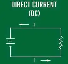
Direct current (DC) is an electric charge that flows consistently in one direction through a conductor.

✅ Provides constant voltage for stable operation

✅ Powers batteries, electronics, and renewable systems

✅ Differs from alternating current by unidirectional flow

Direct current (DC) plays an essential role in electrical power. It is a type of electrical flow where the flow of electric charge remains constant and does not change direction. DC differs from alternating current (AC), periodically reversing direction as the voltages and amperage vary with time. Direct current is often compared with alternating current, which reverses direction periodically and dominates modern transmission systems.

One of the most well-known proponents of direct current was Thomas Edison, who competed with George Westinghouse, an advocate for alternating current, in the late 19th century. Their competition, known as the "War of the Currents," ultimately led to the widespread adoption of AC systems, which are more suitable for long-distance, high-voltage transmission. However, this does not diminish the importance and numerous applications of direct current in modern technology. To better understand how DC works, it helps to review basic electricity concepts such as charge, voltage, and resistance.

A direct current power supply, often found in electronic devices, converts AC power from the power grid into DC power. This conversion process ensures a constant voltage that meets the device's requirements. The conversion is achieved through transformers, rectifiers, and capacitors, which stabilize the voltage and smooth out the electrical signal.

Direct current has various advantages and disadvantages. One of its main advantages is the ability to provide stable, constant power, essential for devices such as computers, smartphones, and other sensitive electronics. Additionally, DC power has lower losses in the form of heat dissipation compared to AC power. On the other hand, a significant disadvantage of DC is its limited capacity for long-distance power transmission. It requires larger conductors to maintain efficiency, and the power loss becomes substantial over long distances. The difference between AC and DC has shaped the history of electricity since the “War of the Currents” between Edison and Westinghouse.

DC motors and generators operate through the principle of electromagnetism. A DC motor converts electrical energy into mechanical energy, while a generator turns mechanical energy into electrical energy. The interaction between a magnetic field and the flow of amperage within conductive wires generates a force, causing the motor's rotor to rotate. In the case of a generator, the mechanical motion induces a flow within the conductive wires.

Battery technology heavily relies on direct current, as batteries store and discharge energy in DC power. This is one reason electric vehicles (EVs) use DC motors and batteries for propulsion. In addition, the growing trend towards renewable energy sources, such as solar panels and wind turbines, further highlights the importance of DC power, as these sources initially generate DC power before converting it to AC for grid integration. For a broader context, you can explore electricity fundamentals, which cover both direct and alternating current and their applications.

Both AC and DC currents can be converted and transmitted through specialized equipment. For example, AC can be converted into DC using rectifiers, while DC can be converted back into AC through inverters. The conversion between these two forms of electricity enables the integration of renewable energy sources into the existing power grid. Additionally, it enables the efficient use of energy storage systems, such as batteries. Many renewable energy systems generate DC first, making them a form of alternative electricity that is later converted to AC for grid use.

DC voltage conversion involves changing the voltage level of a direct current without altering its form. This is typically achieved through DC converters, which either step up (increase) or step down (decrease) the voltage. In many electronic devices, DC converters provide the correct voltage levels required for different components to function optimally.

Direct current can be calculated using Ohm's Law, which states that voltage (V) equals the product of flow (I) and resistance (R). The formula is V = I × R. This fundamental principle is crucial for understanding and analyzing electrical circuits, including those involving direct current.

DC is directly related to electrical resistance, since Ohm’s Law determines how voltage, cpnduction, and resistance interact in a circuit.

Devices like rectifiers and inverters rely on principles explained in Ampere’s Law and Biot-Savart Law, which describe the relationship between electricity and magnetism.


Frequently Asked Questions


What is the best formula to calculate DC electrical stream? 

Ohm's Law is the fundamental principle governing the relationship between voltage, flow, and resistance in an electrical circuit. It is named after German physicist Georg Simon Ohm, who formulated the law in the early 19th century. Ohm's Law can be used to calculate direct (DC) electrical current when the voltage and resistance are known.

The formula for Ohm's Law is:

V = I × R

Where:
V = Voltage (volts)
I = Current (amperes or amps)
R = Resistance (ohms)

This formula can be rearranged to calculate the current (I) when voltage (V) and resistance (R) are given:

I = V / R

Using this formula, we can determine the DC electrical energy flowing through a circuit when the voltage across the circuit and the resistance of the circuit are known.

For example, consider a simple DC circuit with a 12-volt voltage source and a 6-ohm resistor. Using the formula for calculating current, we can determine the amperage flowing through the circuit:

I = V / R
I = 12 V / 6 Ω
I = 2 A

Thus, the DC electrical amperage flowing through the circuit is 2 amperes.

To calculate DC electrical stream, apply Ohm's Law by dividing the voltage (V) by the resistance (R) to determine the current (I) in amperes. Ohm's Law is a fundamental principle in electrical engineering, serving as the basis for understanding and analyzing electrical circuits, including those involving direct current.


Are there fewer losses with the direct current than with the alternating current?

Whether there are fewer losses with direct current (DC) than alternating current (AC) depends on the specific application and context. In certain scenarios, DC can have fewer losses, while AC might be more efficient in others. Below are some examples to illustrate this point:

Transmission losses: In long-distance high-voltage power transmission, direct high-voltage current (HVDC) transmission lines can have fewer losses than traditional AC transmission lines. This is because DC transmission lines do not suffer from reactive power losses or the skin effect (which causes higher resistance in AC lines due to the stream flowing mainly on the conductor's surface). Moreover, HVDC lines can be more efficient over long distances as they require only two conductors, while three are needed for AC transmission lines.

Electronic devices: When it comes to electronic devices like computers and smartphones, as well as other sensitive equipment, DC power is often preferred because it provides stable, constant power, resulting in lower losses in the form of heat dissipation. However, these devices need a conversion from the AC power supplied by the grid to the DC power they require. The conversion process may introduce some losses, but DC can be more efficient for these applications once the power is converted.

Electric power transmission over short distances: AC is typically more efficient than DC for shorter distances and lower voltage levels. AC voltage can be easily transformed to different levels using transformers, which are relatively simple and low-loss devices. In contrast, converting DC voltage levels requires more complex and potentially lossy power electronic converters.

The efficiency of direct and alternating currents depends on the specific application and context. For example, DC power can have fewer losses in some cases, such as HVDC transmission lines and sensitive electronic devices. On the other hand, AC is more efficient for short-distance and lower voltage-level transmission, mainly due to the ease of transforming voltage levels using transformers.


Is direct current safer than alternating current?

The safety of direct current (DC) and alternating current (AC) depends on several factors, including voltage, stream levels, and the specific application. However, it is essential to remember that both types of current can be hazardous under specific conditions.

Both charge flow types are generally considered safe when comparing the safety of DC and AC at low voltages and amps. However, some differences in the physiological effects of DC and AC on the human body can make one type of amperage more hazardous than the other under certain conditions:

Muscle contraction: AC can cause muscle contractions that may make it difficult for a person to release a live wire or conductor. In contrast, DC can also cause muscle contractions, but typically only when making or breaking contact with the conductor. This means that once a person is in contact with a DC source, the muscles may not contract continuously, making it easier to let go.

Ventricular fibrillation: AC has a higher probability of causing ventricular fibrillation (a life-threatening heart rhythm disturbance) than DC at the same energy levels. The frequency of AC power, typically 50 or 60 Hz, can interfere with the electrical signals in the heart, leading to this dangerous condition. DC is less likely to cause ventricular fibrillation because it lacks a frequency component.

Skin resistance: Human skin has a higher resistance to DC than to AC, which can result in less amperage flowing through the body when exposed to DC compared to AC at the same voltage levels. However, this difference in resistance is mostly relevant at low voltages, and the risk of injury still exists when dealing with high-voltage DC sources.

Although there are some differences in the effects of DC and AC on the human body, it is essential to understand that both types of amperage can be dangerous when not handled properly. Therefore, safety precautions must always be taken when working with electrical systems, whether they involve direct or alternating current.

Ultimately, the safety of direct and alternating currents depends on the specific situation and proper handling of electrical systems. However, by following established safety protocols, potential risks associated with both types of amperage can be minimized.


Related Articles


View more

Electricity Deregulation Explained

Electricity deregulation enables competitive energy markets, retail choice, and wholesale power pricing, separating generation from transmission and distribution to enhance grid reliability, lower tariffs, spur innovation, and diversify suppliers for industrial and commercial loads.


What Is Electricity Deregulation?

Electricity deregulation unbundles utilities, enabling market-based generation, retail choice, and efficient pricing.

✅ Unbundles generation, transmission, and distribution functions.

✅ Enables locational marginal pricing and demand response programs.

✅ Promotes independent system operators and competitive wholesale markets.


In The United States, Electricity Deregulation is now more than 15 years into an experiment to deregulate and restructure the electric power generation, transmission and distribution industry. Some claim that it has produced national benefits as much as $30 billion per year. Others claim the change has resulted in penalties as high as $30 billion per year. And still others point to major declines in reliability and increased frequency of blackouts. For context, resources like what electricity is can clarify foundational terms before policy comparisons.

Why are there such broad disagreement about the impact? How do the results of deregulation and restructuring compare with predictions? Has the change benefited our industrial or commercial users, ordinary consumers and our national economy? To determine the answers to these questions, the key changes that were implemented must be reviewed. A primer on electric power systems helps frame how generation, transmission, and distribution interact under different market rules.

The nature of electric power systems requires significant investments in major facilities, typically costing from tens of millions to billions of dollars. These facilities have long construction lead-times, taking years from start to completion, and often remain in service for as long as 40 years. Regulation provided for the return of the investment (depreciation) and the return on the investment (earnings) over the facilities lifetime. These cost-recovery structures ultimately filter into electricity prices that customers see on their bills.

The systems were interconnected to take advantage of the diversity in times of peak use and in times of equipment failures and emergencies. The industry focus was on long-term cost minimization. Decisions were based on life-cycle cost analyses. In such an environment, a high degree of cooperation developed among those involved in owning, managing, planning and operating electric power systems2. The national savings from this cooperation and interconnection were carefully studied many times and had increased to nearly $20 billion annually3 by the late 1980s. Prices to consumers, controlled by state regulators, were reduced by these savings. Such regional coordination also stabilizes electricity supply during peak seasons and emergencies.

Many supporters of this and the introduction of competition into the electric power business believed it would lead to significant economic benefits and price reductions to consumers. The move to have competition replace government regulation gained many adherents, particularly in large industry, where there were concerns over growing foreign competition; with economists in the nation's universities, who welcomed an opportunity to apply their theories; by investment bankers, who saw the huge fees they would earn to finance numerous buyouts and mergers; by lawyers, accounting organizations and some engineers, who saw increased business; and by entrepreneurs, who saw opportunities for huge profits. Some utility executives believed competition would help increase the return to investors that had, at times, been unfairly limited by regulators. Advocates often cited gains in electricity power market efficiency as proof that liberalization could unlock innovation.

In general, those favouring Electricity Deregulation and competition as a driver were not aware of its effect on the benefits of coordination. Most lacked knowledge of power systems functioning and costs. The concept that profits would increase for the suppliers while prices would go down for consumers obviously required major cost reductions. But no analyses of the source of these cost reductions were conducted by competent engineers. Rather, it was the common belief they would result from increased competition. They sometimes conflated consumer-level tactics like how to save electricity with systemic cost drivers in bulk power operations.

Have such cost reductions occurred? The answer is clearly no. There have been some improvements in generator unit availability and efficiency. On the other hand, there have been huge additional costs and cost increases stemming from the reduced benefits of coordination, the increased complexity of the system, scheduling, and other operating procedures. For end users, focusing on saving electricity can mitigate bill impacts even as market-level costs fluctuate.


Related Articles

View more

Total Impedance Calculator

Total impedance calculator determines total opposition in AC circuits by combining resistance, inductive reactance, and capacitive reactance. Input R, L, C, and frequency to find Z in ohms for accurate analysis in power distribution, filters, or signal systems.


Quick Definition: Total Impedance Calculator

  • Purpose: Calculates total opposition (impedance) in AC circuits by combining resistance and reactance.

  • Functionality: Processes inputs like resistance (R), inductance (L), capacitance (C), and frequency to compute impedance (Z).​

  • Applications: Used in designing power supplies, signal transmission systems, and optimizing filter performance.​


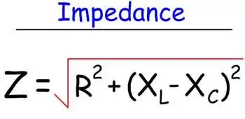
A total impedance calculator helps you quickly determine the combined impedance of resistors, inductors, and capacitors in AC circuits. By inputting values for resistance (R), inductive reactance (XL), and capacitive reactance (XC), you can calculate total impedance (Z) for both series and parallel configurations, making circuit analysis faster, more accurate, and easier to understand. A total impedance calculator is a powerful tool used by electrical engineers, technicians, and students to determine the impedance in RLC circuits, whether in series or parallel. These calculators simplify complex calculations involving resistance, inductance, and capacitance by processing formulas that would otherwise require manual computation with complex numbers.

Whether you are designing a power supply, analyzing signal transmission, or optimizing filter performance, a total impedance calculator helps ensure accuracy and efficiency. It is especially valuable when analyzing the behaviour of AC circuits across different frequency ranges in hertz.


What Is Total Impedance?

Total impedance refers to the combined opposition that a circuit presents to the flow of alternating current. It takes into account both resistance (R) and reactance (X), expressed as a single value in ohm (Ω). The two primary types of reactance are:

  • Inductive reactance (caused by coils or inductors)

  • Capacitive reactance (caused by capacitors)

These values change depending on the circuit's frequency, making tools like a total impedance calculator essential for real-time circuit analysis.


Who Uses a Total Impedance Calculator?

  • Electrical engineers use it in power systems, communications, and control circuits.

  • Technicians rely on it to verify component ratings and troubleshoot systems.

  • Educators and students apply it in academic settings for lab work and theoretical analysis.

  • Industrial maintenance professionals use it to evaluate equipment behavior under various loads.

It is particularly helpful when working with an RLC circuit impedance calculation where both inductance (L) and capacitance (C) are present.


What Does a Total Impedance Calculator Do?

A good impedance calculator lets you:

  • Enter known values like resistance (R), inductance L and capacitance C, and frequency in hertz.

  • Automatically compute impedance for either series RLC circuit or parallel RLC circuit setups.

  • Show results using the correct impedance formula, including both magnitude and phase.

  • Factor in angular frequency in rad, derived from ω=2πf\omega = 2\pi fω=2πf, where fff is frequency.

  • Solve expressions like 1ωC\frac{1}{\omega C}ωC1​ or frac 1 omega, commonly used in capacitive reactance calculations.

The result is a fast, accurate way to determine the impedance and analyze AC circuit behavior.


Key Concepts Behind the Calculator


1. Impedance Formula (Z)

This requires working with complex numbers to calculate both magnitude and phase angle.


2. Reactance Components

  • Inductor and capacitor components contribute to the reactive part of the impedance.

  • Capacitive reactance

  • Inductive reactance

These values vary with frequency and affect circuit resonance and behavior.


Why Use a Total Impedance Calculator?

Without a calculator, these formulas can be tedious to evaluate manually—especially when working in real time or across wide frequency in hertz ranges. A calculator ensures:

  • Greater accuracy in design and testing

  • Time-saving analysis for troubleshooting

  • Safer decision-making for load balancing and component selection

In power electronics, knowing the rlc circuit impedance helps prevent equipment damage and improves system efficiency.

A total impedance calculator is an essential tool for modern electrical work. It brings together the core principles of AC circuit analysis—resistance, inductance, capacitance, and frequency—into one user-friendly interface. Whether you're designing systems, teaching students, or maintaining equipment, using this tool helps you quickly and reliably calculate the impedance and make informed decisions.


Related Articles


View more

Electromagnetic Induction

Electromagnetic induction is the process of generating electric current by changing a magnetic field, forming the basis for transformers, generators, and electric motors in power generation and energy conversion systems.


What is Electromagnetic Induction?

Electromagnetic induction is a fascinating and vital concept shaping how we generate, transfer, and utilize electricity.

✅ Process where a changing magnetic field induces an electric current in a conductor

✅ Fundamental principle behind transformers, generators, and electric motors

✅ Essential for modern power generation, transmission, and energy conversion


Its underlying principles, Faraday's Law and Lenz's Law, explain the phenomena occurring when magnetic fields interact with conductors. At the same time, its various applications, such as electric generators, transformers, induction heating, and wireless charging, have revolutionized our daily lives. As we continue to explore and understand this intricacy, we can look forward to even more innovations and advancements in electricity and magnetism. Understanding Faraday's Law is essential to grasp how changing magnetic fields generate electricity through electromagnetic induction.


Fundamental Laws of Electromagnetic Induction

Faraday's Law of electromagnetic induction, invented by Michael Faraday, is a key principle that states that the induced EMF in a coil is proportional to the rate of change of the magnetic flux (dφ/dt) passing through the coil. The more rapidly the magnetic field changes, the higher the amount of voltage induced will be. This relationship between electricity and magnetism laid the foundation for the development of various electrical devices and systems. The relationship between electricity and magnetism forms the foundation of generators, transformers, and other key electrical systems.

Lenz's Law, another crucial principle, explains the direction of the induced current. It states that the induced current will always flow in a direction that opposes the change in magnetic flux, acting as a stabilizing electromotive force. By combining Faraday's and Lenz's Law, we can better understand how it operates in real-world applications. For a deeper understanding of how voltage is produced in coils, explore the principles of Lenz's Law.


Core Applications: Generators and Transformers

One notable application is the electrical generator, which converts mechanical energy into electrical energy. In a typical generator, a coil of wire rotates within a magnetic field, creating a changing magnetic flux. This change induces a voltage and current in the coil, generating electricity. Generators are commonly used in power plants, automobiles, and other devices requiring a continuous electrical supply. A three-phase transformer uses electromagnetic induction to efficiently transfer power between circuits at different voltages.

Another critical application is the transformer, which transfers electrical energy between circuits with different voltages. Transformers consist of two induction coils wrapped around a shared magnetic core. When an alternating current flows through the primary coil, it creates a magnetic field that induces a voltage in the secondary coil. By adjusting the number of turns in the coils, transformers can step up or down the voltage as needed for specific electrical systems.


Special Phenomena: Eddy Currents, Mutual Inductance, and Self-Inductance

Eddy currents are an intriguing aspect of electromagnetic induction. These currents form when a magnetic field changes, causing swirling, closed loops of electric current within a conductor. Eddy currents generate heat and can lead to energy losses in electrical systems, but they also have practical applications, such as in metal detectors and induction heating. Devices that use electromagnetic induction, such as electric motors, rely on core principles of inductance to regulate energy transfer.

Two critical aspects of electromagnetic induction are mutual inductance and self-inductance. Mutual inductance occurs when the current in one coil induces a voltage in a nearby coil due to their shared magnetic field. Self-inductance refers to a coil's ability to induce a voltage within itself when the current flowing through it changes. Understanding these concepts is crucial for designing and analyzing complex electrical circuits and systems.


Demonstrating the Principle: Coil and Magnet Interaction

In many cases, it involves the interaction of a coil and a magnet, either a permanent magnet or an electromagnet. A bar magnet, for example, may be moved near a coil, or the coil may be moved about the magnet. This motion changes the magnetic field and induces a voltage in the coil, demonstrating the dynamic relationship between electricity and magnetism. Learning the basics of electrical resistance helps explain how eddy currents generate heat in conductive materials.


Modern Impact and Emerging Technologies

It has an immense impact on modern life, from generating electricity in power plants to operating devices like transformers, electric motors, and wireless chargers. The principles of Faraday's Law and Lenz's Law help explain the complex phenomena that occur when magnetic fields interact with conductors. By harnessing these principles, scientists and engineers have created various practical applications that have revolutionized our daily lives.

Electromagnetic induction demonstrates the fundamental relationship between electricity and magnetism and is integral to many aspects of our modern world. Faraday's Law and Lenz's Law underpin this phenomenon, governing the induced voltage and current when magnetic fields change. The applications of electromagnetic induction range from electric generators and transformers to the study of eddy currents, mutual in influence and self-inductance. By understanding these principles, we can continue to innovate and develop new technologies to improve our daily lives and advance our understanding of the world.


Induction Heating

Electromagnetic induction heating is another practical application that relies on electromagnetic induction. This technology utilizes eddy currents to heat conductive materials, such as metals. By placing a conductive material within a rapidly changing magnetic field, eddy currents are generated within the material, producing heat due to their resistance. This heating method has been employed in various industrial processes, including metal hardening, welding, and cooking.

Wireless charging is an emerging technology that utilizes electromagnetic induction to transfer energy between two coils. When an electric current flows through the primary coil, it generates a magnetic field, which induces a voltage in the secondary coil, providing power to the device. This technology has seen increasing adoption in recent years, particularly for charging electric vehicles and smartphones, offering convenience and reduced dependence on cords and cables.


Related Articles


View more

Sign Up for Electricity Forum’s Newsletter

Stay informed with our FREE Newsletter — get the latest news, breakthrough technologies, and expert insights, delivered straight to your inbox.

Electricity Today T&D Magazine Subscribe for FREE

Stay informed with the latest T&D policies and technologies.
  • Timely insights from industry experts
  • Practical solutions T&D engineers
  • Free access to every issue

Download the 2025 Electrical Training Catalog

Explore 50+ live, expert-led electrical training courses –

  • Interactive
  • Flexible
  • CEU-cerified