Three Phase Electricity Explained


Three Phase Electricity

Three phase electricity delivers power using three alternating currents that are offset in phase. It provides consistent and efficient energy for industrial, commercial, and high-load applications, improving stability and reducing conductor size.


What is Three Phase Electricity?

Three phase electricity is a power system that uses three alternating currents, each offset by 120 degrees, to deliver constant power flow.

✅ Delivers more efficient and stable power than single-phase systems

✅ Ideal for large motors, commercial buildings, and industrial equipment

✅ Reduces conductor material and energy loss over long distances


Three phase voltage, frequency and number of wires

Three phase electricity is the dominant method of electrical power generation, transmission, and distribution across the industrialized world. Unlike single-phase systems, which rely on a single alternating current, three-phase systems use three separate currents, each 120 degrees out of phase with the others. This setup provides a consistent and balanced power flow, making it significantly more efficient for high-demand applications, such as motors, transformers, and large-scale infrastructure. Understanding the difference between alternating current and direct current is essential to grasp how three-phase systems deliver constant power using offset waveforms.


Understanding the Concept

At the heart of a three-phase system are three sinusoidal waveforms, evenly spaced to maintain a continuous flow of energy. When one phase reaches its peak, the others are in different parts of their cycle, ensuring that at any given moment, some power is being delivered. This creates what is known as constant power transfer, a major advantage over single-phase systems that experience power dips between cycles. Since three-phase systems rely heavily on accurate current flow measurement, it’s important to know what ammeters measure and how they help monitor system balance.

For industrial and commercial operations, this stability translates to increased energy efficiency, extended equipment lifespan, and reduced operating costs. Large electric motors, for example, run more smoothly on three-phase power, which avoids the surging and vibration commonly associated with single-phase inputs.


A Brief History

Three phase electricity wasn’t invented by a single person but emerged through the contributions of several pioneers in the late 19th century. Galileo Ferraris in Italy, Nikola Tesla in the United States, and Mikhail Dolivo-Dobrovolsky in Europe all played crucial roles in developing and refining the idea of three-phase alternating current. Tesla’s patents and Dolivo-Dobrovolsky’s practical systems laid the groundwork for what is now a global standard. Engineers use wattmeters to accurately measure real power in three-phase systems, while Watts Law helps calculate the relationships between voltage, current, and power.


Wye and Delta Configurations

Three-phase systems are typically wired in one of two configurations: the Wye (Y) or Delta (Δ) configuration. Each has specific advantages depending on the application:

  • In a Wye connection, each phase is tied to a central neutral point, allowing for multiple voltage levels within the same system. This is common in both commercial and residential applications, where both high and low voltages are required.

  • A Delta connection utilizes a closed loop with no neutral, a configuration commonly found in industrial setups. It delivers the same voltage between all phases and is ideal for running large motors without needing a neutral return path.

One of the most important relationships in these configurations is the √3 ratio between line voltage and phase voltage, a fundamental aspect that engineers use in calculating load, cable sizing, and protective device coordination.


Technical Benefits

Three-phase systems have built-in advantages that go beyond stability. Because the sum of the three phase currents is zero in a balanced load, a neutral wire is often unnecessary. This reduces the amount of conductor material needed, lowering costs and simplifying design. Additionally, three-phase motors naturally create a rotating magnetic field, eliminating the need for external circuitry to start or maintain rotation.

Another major benefit is that power output remains consistent. In single-phase systems, power drops to zero twice per cycle, but three-phase systems deliver non-pulsating power, which is especially important in sensitive or precision equipment. The function of a busbar is especially important in three-phase distribution panels, helping to manage multiple circuit connections efficiently.


Where and Why It’s Used

While most homes use single-phase electricity, three-phase is the standard in virtually all commercial and industrial environments. Factories, data centers, hospitals, and office buildings rely on it to power everything from HVAC systems and elevators to conveyor belts and industrial machines.

Three-phase is also common in electric vehicle (EV) charging stations and renewable energy systems, where efficient, high-capacity delivery is essential. If you're working with three-phase motors or transformers, knowing the role of a conductor and how electrical resistance affects current flow is fundamental to efficient design.

For sites that only have access to single-phase power, phase converters—whether rotary or digital—can simulate three-phase conditions, enabling them to operate three-phase equipment. This flexibility has made three-phase solutions accessible even in remote or rural areas. Three-phase systems often operate at medium voltage, especially in commercial settings, and their stability can reduce the risks of ground faults.


Voltage Levels and Color Codes

Depending on the region, the standard line and phase voltages vary. In North America, typical voltage values include 120/208 volts and 277/480 volts, whereas in Europe and much of Asia, 230/400 volts is more common. Wiring color codes also differ: red/yellow/blue in Europe, black/red/blue in North America, and other variations depending on the country's electrical code. These standards ensure safety, compatibility, and ease of troubleshooting.


The Global Standard for Power

Three-phase electricity is not just a technical solution; it is the foundation of modern electrical infrastructure. Its ability to deliver large amounts of power efficiently, safely, and reliably has made it the system of choice for more than a century. From powering the machines that build our world to the systems that keep us connected, three-phase electricity remains indispensable.


Related Articles


Related News

Active Power

Active power is the actual energy consumed by electrical equipment to perform useful work, such as lighting or running motors. It is measured in kilowatts (kW) and is essential for efficient power system design, load management, and energy billing accuracy.


What is "active power"?

Active power is the real power consumed in an AC circuit to perform useful work.

✅ Measured in kilowatts (kW)

✅ Powers resistive loads like heaters, lights, and motors

✅ Crucial for calculating energy usage and efficiency


In AC circuits, active power (P) refers to the component of electrical power that results in energy transfer to a load. It is the energy that performs work—such as producing motion, light, or heat—and is distinct from reactive power, which oscillates between source and load without being consumed.

Active Power Formula

The general formula for active power is:

P = VIcosθ

Where:

  • P = Active Power (watts)

  • V = RMS Voltage

  • I = RMS Current

  • θ = Phase angle between voltage and current

In real-world power systems, only the portion of the current in phase with the voltage contributes to active power. The portion out of phase results in reactive power and does not produce usable energy.


Equation 1


The above active power equation is valid for both sinusoidal and nonsinusoidal conditions. For sinusoidal condition, '1rn, resolves to the familiar form,


Equation 2


Sinusoidal and Non-Sinusoidal Conditions

The calculation of active power can differ slightly depending on waveform distortion:

  • For sinusoidal conditions, Equation 1 simplifies to the standard P = VIcosθ form.

  • For non-sinusoidal waveforms, the total active power includes the sum of contributions from all harmonic components. However, since voltage distortion is typically below 5% in most power systems, the simplified equation is usually accurate enough for practical purposes.


Real-World Example

A standard incandescent light bulb converts electrical power into visible light and heat. This is a classic case of active power at work—where the current and voltage are in phase, and virtually all supplied power is consumed usefully.


Active vs Reactive vs Apparent Power

It’s important to distinguish active power from related concepts:

  • Reactive Power (Q): Energy exchanged but not consumed, measured in kVAR.

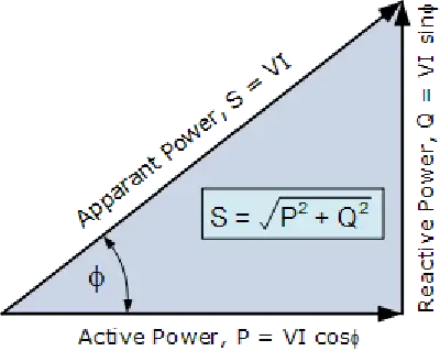
  • Apparent Power (S): The vector sum of active and reactive power, measured in kVA.

  • Power Factor: The ratio of active power to apparent power (PF = P/S).

While active power does the real work, apparent power impacts system loading and reactive power affects voltage stability. See our power factor training for more.


Measurement and Application

Active power is typically measured using true RMS meters that calculate the average of the instantaneous product of voltage and current. Advanced power analyzers now offer direct measurement of real power in both clean and distorted systems.

Engineers use active power data for:

  • Energy consumption analysis

  • Load management and optimization

  • System efficiency evaluation

  • Compliance with energy standards


Related Reading


Frequently Asked Questions


What is active power used for?

Active power is used to perform real work in electrical systems, such as lighting, heating, and running motors.


Is active power the same as real power?

Yes. Active power, real power, and true power are interchangeable terms that refer to the same concept.


How is active power calculated?

It is calculated using the formula P = VIcosθ, where V and I are RMS voltage and current, and θ is the phase angle between them.

In summary, understanding active power is essential for designing efficient electrical systems and ensuring energy accountability. By distinguishing it from reactive and apparent power, professionals can improve system performance and reduce energy losses.


Related Articles


View more

Geothermal Electricity Explained

Geothermal electricity delivers renewable baseload power by converting subsurface heat through turbines, generators, ORC binary cycles, and heat exchangers, enabling grid integration, high capacity factor, low emissions, and efficient power plant control systems.


What Is Geothermal Electricity?

Geothermal electricity converts geothermal heat to power using turbines and generators for low-emission baseload.

✅ Uses steam, flash, and binary cycle power plant designs

✅ Employs ORC, heat exchangers, and closed-loop systems

✅ Provides baseload, high capacity factor, and grid stability


Geothermal Electricity is produced through geothermal power plants capturing the thermal energy contained in the Earth. Use of geothermal energy is based thermodynamically on the temperature difference between a mass of subsurface rock and water and a mass of water or air at the Earth's surface. This temperature difference allows production of thermal energy that can be either used directly or converted to mechanical or Geothermal Electricity. For context on broader methods and terminology, see this overview of electricity generation and how heat energy is converted to power.

Commercial exploration and development of Plant Geothermal water generated into Electricity to date have focused on natural geothermal reservoirs—volumes of rock at high temperatures (up to 662°F or 350°C) and with both high porosity (pore space, usually filled with water) and high permeability (ability to transmit fluid). The thermal energy is tapped by drilling wells into the reservoirs. The thermal energy in the rock is transferred by conduction to the fluid, which subsequently flows to the well and then to the Earth's surface where it can be converted into Geothermal Electricity. This well-to-turbine pathway is a fundamental part of electricity production from thermal resources.

There are several types of natural geothermal reservoirs. All the reservoirs developed to date for electrical energy are termed hydrothermal convection systems and are characterized by circulation of meteoric (surface) water to depth. The driving force of the convection systems is gravity, effective because of the density difference between cold, downward-moving, recharge water and heated, upward-moving, thermal water. A hydrothermal convection system can be driven either by an underlying young igneous intrusion or by merely deep circulation of water along faults and fractures. Depending on the physical state of the pore fluid, there are two kinds of hydrothermal convection systems: liquid-dominated, in which all the pores and fractures are filled with liquid water that exists at temperatures well above boiling at atmospheric pressure, owing to the pressure of overlying water; and vapor-dominated, in which the larger pores and fractures are filled with steam. Liquid-dominated reservoirs produce either water or a mixture of water and steam, whereas vapor-dominated reservoirs produce only steam, in most cases superheated. Because water acts as the primary working fluid in most systems, understanding the interplay of water and electricity helps clarify operational safety and design.

These hydrothermal systems are distinct from hydroelectricity produced by river impoundments, even though both ultimately rely on water as a medium.

Although geothermal energy is present everywhere beneath the Earth's surface, its use is possible only when certain conditions are met: (1) The energy must be accessible to drilling, usually at depths of less than 2 mi (3 km) but possibly at depths of 4mi (6–7km) in particularly favorable environments (such as in the northern Gulf of Mexico Basin of the United States). (2) Pending demonstration of the technology and economics for fracturing and producing energy from rock of low permeability, the reservoir porosity and permeability must be sufficiently high to allow production of large quantities of thermal water. (3) Since a major cost in geothermal development is drilling and since costs per meter increase with increasing depth, the shallower the concentration of geothermal energy the better. (4) Geothermal fluids can be transported economically by pipeline on the Earth's surface only a few tens of kilometers, and thus any generating or direct-use facility must be located at or near the geothermal anomaly. When these conditions align, engineered systems can efficiently generate electricity from accessible geothermal gradients.

The use of geothermal energy for Geothermal Electricity has become widespread because of several factors. Countries where geothermal resources are prevalent have desired to develop their own resources in contrast to importing fuel for power generation. In countries where many resource alternatives are available for power generation, including geothermal, geothermal has been a preferred resource because it cannot be transported for sale, and the use of geothermal energy enables fossil fuels to be used for higher and better purposes than power generation. Also, geothermal steam has become an attractive power generation alternative because of environmental benefits and because the unit sizes are small (normally less than 100 MW). Moreover, geothermal plants can be built much more rapidly than plants using fossil fuel and nuclear resources, which, for economic purposes, have to be very large in size. Electrical utility systems are also more reliable if their power sources are not concentrated in a small number of large units. In energy planning, geothermal is often evaluated alongside other forms of alternative electricity to balance portfolios and grid resilience. Many developers also highlight its contribution to green electricity targets thanks to low lifecycle emissions.


Related Articles

View more

Capacitance in Series

Capacitance in series reduces overall capacitance by summing the reciprocals of each capacitor. This concept is essential in electronics, circuit analysis, and power systems, ensuring proper charge storage, voltage division, and reliable circuit performance.


What is Capacitance in Series?

When capacitors are connected in series, their combined behavior follows specific rules that affect voltage distribution, total capacitance, and charge consistency.

✅ Reduces total capacitance as capacitors share the voltage

✅ Total capacitance is calculated using the reciprocal formula

✅ Charge on each capacitor is equal in a series circuit


In a series circuit, connecting more than one capacitor in series affects how voltage and charge are distributed, directly impacting the total capacitance of the system. Unlike parallel arrangements, a series setup reduces the overall capacitance and requires the use of a reciprocal formula to calculate the correct value. This configuration functions like a voltage divider, where the total voltage is split across each capacitor based on its individual capacitance. While this reduces the system’s ability to store charge, it also controls how voltage is allocated, which is useful in applications where precise energy storage and voltage regulation are needed.

For a clearer technical explanation, see our what is capacitance page, which breaks down how this key property affects circuit design.

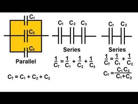
When working with individual capacitors in electronic circuits, it is essential to understand their behaviour and effects. For example, in a series arrangement, the positive plate of one capacitor is connected to the negative plate of the next capacitor in line. This unique connection affects the circuit's total equivalent capacitance (C_total), resulting in a total capacitance that is smaller than the smallest individual capacitance (C) present in the series. The total capacitance of capacitors in series is always less than the value of the smallest individual capacitor in the arrangement.

A series circuit is characterized by its linear sequence of components, through which the current flows in a single path. In such circuits, the total voltage is distributed across each component in proportion to its resistance. The overall resistance of a series circuit is equal to the sum of the individual resistances of the connected components. The unit of capacitance, the farad, measures a capacitor’s ability to store electric charge per unit voltage.

When they are connected in series, the total C of the circuit is affected. This is because the positive plate of the capacitors is connected in series to the total C. Each capacitor stores the same charge in this arrangement, and the total voltage is divided across the capacitors in proportion to their C. This characteristic of series-connected capacitors plays a significant role in designing electronic circuits that require specific voltage and charge distribution properties. To fully grasp how capacitors behave in series, it’s important to understand what is a capacitor and how it stores and releases electrical energy.


Capacitors in Series: Formula, Voltage, and Charge Characteristics

Feature Capacitors in Series
Total Capacitance Less than the smallest individual capacitor
Formula 1/Ctotal = 1/C₁ + 1/C₂ + 1/C₃ + ...
Voltage Distribution Voltage divides across capacitors based on capacitance values
Charge on Capacitors Same charge on all capacitors
Use Case Used when reduced overall capacitance is needed in a circuit
Energy Storage Lower total energy storage than a single capacitor with same voltage


Different types of capacitors, such as ceramic or electrolytic, behave differently in series configurations based on their construction and rated voltage.


Formula for Calculation

To accurately calculate the total C of capacitors connected in series, the following formula is employed:

C_total = 1 / (1/C1 + 1/C2 + 1/C3 + ... + 1/Cn)

This formula calculates the inverse of the total C. To find the actual total C, take the inverse of the sum of the inverse individual capacitances. This mathematical process enables the precise determination of the overall capacitance value in a series configuration, which is crucial when designing or analyzing electronic circuits.


Impact of the Smallest Capacitor on Total Capacitance

When several are connected in series, the total C becomes smaller than the smallest individual C. This phenomenon occurs because the capacitor with a smaller capacitance (C) limits the total capacitance (C), acting as a bottleneck for current flow and restricting the total charge stored in the circuit. Understanding this limiting effect is critical when selecting capacitors for a series configuration, as the smallest capacitor will significantly impact the overall performance of the electronic circuit. Engineers must also consider electrical resistance, which affects how current and voltage behave in conjunction with capacitors in mixed-component circuits.


Comparing Capacitors in Parallel and Series Configurations

In contrast to capacitors in series, when capacitors are connected in parallel, the total C is the sum of the individual capacitances. This difference occurs because each capacitor is directly connected to the power source in a parallel circuit, allowing it to store its charge independently. Consequently, capacitors in parallel configurations offer higher overall capacitance values, making them suitable for applications that require increased charge storage capabilities. Reviewing electrical resistance definition can help clarify how resistance and C work together in impedance-sensitive designs. You can explore how capacitance in parallel differs from series configurations when designing circuits requiring larger energy storage.


Equivalent Capacitance and Voltage Drop in Series Capacitors

The equivalent C of capacitors connected in series can be determined by dividing the total charge stored in the circuit by the total voltage across the circuit. This is because the total charge stored in the circuit equals the sum of the charges on each capacitor. In contrast, the total voltage is calculated to determine the total capacitance for the number of capacitors connected.

The voltage drop in capacitors connected in series is divided among the capacitors in proportion to their C. This means that the voltage across each capacitor is proportional to its C. Understanding the voltage drop distribution in series capacitors is essential when designing circuits that rely on specific voltage levels across components.


Replacing Capacitors in Series with a Single Equivalent Capacitor and Combination Circuits

In some cases, capacitors in series can be replaced with a single equivalent capacitor that has the same C value as the equivalent capacitance of the series capacitors. This replacement technique can simplify circuit design and analysis, consolidating multiple components into a single element with equivalent electrical properties.

In a combination circuit, capacitors are connected in both series and parallel configurations. These complex arrangements are commonly found in practical electronic applications, as they offer more flexibility and adaptability in achieving desired circuit properties. To calculate the total C of a combination circuit, first, compute the capacitance of each series combination, then add those capacitances to find the total C. This process may involve several steps, as the designer needs to consider the contributions of both series and parallel components to the overall C value.


Applications and Considerations of Capacitors in Series

Capacitors in series configurations are utilized in various electronic applications, such as power supply filtering, signal coupling, and decoupling, as well as in tuning and timing circuits. When designing these applications, engineers must consider the capacitors' voltage ratings, tolerances, temperature coefficients, and other parameters to ensure the circuit functions as desired.

One crucial consideration when working with capacitors in series is the voltage rating. The voltage rating of each capacitor must be sufficient to handle the voltage that will be applied across it. Since the total voltage is distributed among the capacitors in series, selecting capacitors with appropriate voltage ratings is essential to prevent component failure or degradation.

Another important consideration is the capacitors' tolerances, which indicate the possible variation in C values from their nominal specifications. Capacitors with tighter tolerances may be required for precise applications, as variations in C values can impact the overall performance of the electronic circuit. 


Related Articles


View more

Equivalent Resistance

Equivalent resistance is the total resistance of a circuit that simplifies multiple resistors into a single resistor. It is calculated differently for series and parallel circuits, helping determine current flow, voltage distribution, and overall power consumption in electrical networks.


What is Equivalent Resistance?

Equivalent resistance is a crucial concept for individuals working with electrical circuits. It: 

✅ Represents the single resistance that replaces multiple resistors in a circuit.

✅ Simplifies calculations of current, voltage, and power.

✅ Found using series or parallel formulas based on resistor arrangement.

By mastering the calculation methods for series and parallel circuits, understanding the relationship with Ohm's law, and applying Kirchhoff's laws in more complex situations, you can efficiently analyze and design electrical systems that meet the requirements of various applications. Furthermore, by incorporating equivalent resistance calculations into your skillset, you'll be better prepared to tackle the exciting challenges presented by the ever-evolving world of electronics and power systems.


Equivalent Resistance in Series vs. Parallel Circuits

Configuration Formula Key Characteristics Example Calculation
Series R_eq = R1 + R2 + R3... Same current flows through all resistors; total resistance increases; voltage drop varies across components. For R1=4Ω, R2=6Ω: R_eq = 4Ω + 6Ω = 10Ω
Parallel 1/R_eq = 1/R1 + 1/R2 + 1/R3... Same voltage across each resistor; total resistance decreases; current divides among paths. For R1=4Ω, R2=6Ω: 1/R_eq = 1/4 + 1/6 = 0.416 → R_eq ≈ 2.4Ω

To calculate the equivalent resistance of a network, it is often necessary to determine the sum of the individual resistances. This involves adding the resistance values of each individual resistor in the network, providing a baseline for further calculations. This is a resistance formula for a single resistor, as well as for calculating resistors connected in parallel or in series.

Electrical resistance (R) is a measure of the opposition to the flow of electric current within a circuit. It is determined by the material and dimensions of the conductor, as well as the temperature and other environmental factors. It is measured in ohms (Ω), with lower R indicating greater conductivity and vice versa.


Equivalent Resistance Formula

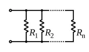
When a group of resistors is connected end-to-end, they form a series. In a series circuit, the total resistance is equal to the sum of the individual Rs, as current must flow through each resistor in turn. The equivalent resistance of a series circuit is calculated by adding the values of each individual resistor:

Req = R1 + R2 + R3 + ...

Resistors connected across the same potential difference, or applied voltage, are referred to as being connected in parallel. In a parallel circuit, the total R is less than the R of any individual resistor as the current divides among the resistors. The equivalent resistance of a parallel circuit is calculated using the reciprocal formula:

1/Req = 1/R1 + 1/R2 + 1/R3 + ...

Equivalent resistance is the single R value that can replace a group of resistors in a circuit, offering the same overall R. This simplifies circuit analysis and allows for more straightforward calculations of current and voltage values.

Ohm's law is an essential principle in electronics and relates closely to equivalent resistance. Ohm's law states that the current (I) flowing through a resistor is directly proportional to the applied voltage (V) and inversely proportional to the R. The equation is:

V = IR

By calculating equivalent resistance for a given circuit, we can use Ohm's law to determine the overall current flowing through the circuit and the voltage drops across each resistor.


Series and parallel circuits exhibit different properties when it comes to equivalent resistance. In series circuits, the overall R increases with the addition of more resistors, which means the total current will decrease. In parallel circuits, adding more resistors results in a decrease in total resistance, causing an increase in total current. Understanding these differences is crucial for designing circuits that meet specific electrical requirements.


Kirchhoff's Law

Kirchhoff's laws are another essential tool for calculating equivalent resistance in more complex circuits that cannot be simplified as purely series or parallel. Kirchhoff's current law (KCL) states that the sum of currents entering a junction in a circuit must equal the sum of currents leaving the junction. Kirchhoff's voltage law (KVL) asserts that the sum of the voltages around any closed loop in a circuit must equal zero. By applying these laws, we can create a system of equations to solve for unknown resistance values in a network, ultimately determining the equivalent resistance.


Real-World Applications

Real-world applications of equivalent resistance can be found in various fields, such as electronics, power distribution, and telecommunications. For example, various components have different R values in electronic devices, such as smartphones. Calculating the equivalent resistance enables engineers to design efficient power management systems, ensuring optimal performance and extended battery life. In power distribution networks, equivalent resistance calculations are essential for determining voltage drops and current values across transmission lines, enabling the design of efficient and reliable power delivery systems.

Understanding equivalent resistance is vital for professionals and students who deal with electrical circuits. From simplifying complex networks to designing efficient circuits, equivalent resistance plays a central role in analyzing and developing modern electronic systems. Familiarity with this concept and associated principles like Ohm's law and Kirchhoff's laws ensures a strong foundation for anyone working with electronics, power systems, and telecommunications.


Technology Advances

As technology advances, the importance of equivalent resistance in designing and analyzing new devices and systems will only grow. Calculating and understanding equivalent resistance enables engineers to push the boundaries of innovation and improve upon existing systems, resulting in more efficient, high-performance solutions for consumers and industries alike.

To further develop your understanding of equivalent resistance and related concepts, consider exploring the wealth of educational resources available online and in textbooks, as well as seeking hands-on experience through workshops or real-world projects. Applying this knowledge to practical scenarios will enable you to tackle various electrical and electronic challenges.

Related Articles


View more

Voltage Drop Calculator

A voltage drop calculator helps electricians and engineers estimate line loss, wire size, and circuit efficiency. By inputting conductor length, current, and material, it ensures proper electrical design, safe voltage regulation, and compliance with power distribution standards.


What is a Voltage Drop Calculator?

A voltage drop calculator (VDC) is crucial for any electrical engineer or designer. It enables them to calculate VD accurately, which is essential for maintaining an efficient and safe electrical system.

✅ Quickly estimates voltage loss in electrical circuits

✅ Helps select the correct wire size for load and distance

✅ Supports NEC code compliance and system efficiency


Power Quality Analysis Training

Power Factor Training

Request a Free Power Quality Training Quotation

Voltage drop calculators are used in various applications, including residential, commercial, and industrial settings, and offer several benefits, such as accurate calculations, time savings, cost reduction, and hazard prevention. Additionally, engineers can ensure the electrical system operates efficiently and safely by considering factors such as cable sizing, wire gauge, and the type of conductor used. Want the full math? Visit our voltage drop formula guide for detailed equations and examples.

There are numerous VDCs available on the internet, and one of the best places to find them is on Google Play.


Applications of Voltage Drop Calculators

VDCs are used in various residential, commercial, and industrial applications. For instance, in residential applications, VDCs help determine the appropriate wire size for the electrical service panel, the length of wires, and the type of installation, ensuring that the electrical system operates correctly and safely. Additionally, VD formulas can be used to calculate resistance and reactance in both single-phase and three-phase electrical systems. It is measured in feet over a specified length.

In commercial applications, voltage drop calculators are used to design and maintain electrical systems in buildings such as hospitals, schools, and offices. These buildings require careful design to ensure that they meet the power requirements of the building and are safe for occupants. VDCs play a crucial role in this process by calculating the VD in the circuit and determining the appropriate wire size and other specifications.

In industrial applications, VDCs are used to design and maintain electrical systems in factories and other industrial settings. These systems require careful design to ensure they meet the equipment's power requirements and are safe for workers. VDCs determine the circuit's VD, the appropriate wire size, and other specifications to ensure that the electrical system operates efficiently and safely. For an overview of the general principles of voltage drop across AC and DC systems, read our article.


Benefits of Using a VDC

Using a VDC offers several benefits, including:

Accurate Calculations: VDCs use complex algorithms to calculate VD accurately. This ensures that the electrical system operates efficiently and safely.

Saves Time: VDCs save time by automating the process of calculating VD. This allows engineers to focus on other aspects of the design process, such as equipment selection and installation.

Reduces Costs: By accurately calculating VD, engineers can select the appropriate wire size and other specifications, thereby reducing the cost of the electrical system.

Prevents Hazards: Accurate calculation of VD prevents electrical hazards, including fires and shocks. 


FREE Voltage Drop Calculator 


Cable Sizing and Wire Gauge

One of the most critical factors to consider when designing an electrical system is cable sizing and wire gauge. The conductor's or wire gauge's size is critical in determining the amount of current that can flow through the conductor without causing excessive VD or overheating. American Wire Gauge (AWG) is the standard system used to specify wire sizes, providing a range of conductor sizes based on the wire's cross-sectional area. Additionally, the National Electrical Code (NEC) provides guidelines for ampacity and voltage drop (VD) for various conductor sizes and types of installations.


Copper or Aluminum Conductors

The type of conductor used in an electrical system also affects the voltage drop (VD). Copper and aluminum conductors are the most commonly used materials, with copper being preferred due to its lower resistance and higher conductivity. However, aluminum conductors are less expensive and commonly used in larger conductors and power transmission lines.


Frequently Asked Questions


How do I calculate voltage drop?

To calculate VD, you can use the VD formula, which is V = IR, where V is the voltage drop, I is the current flowing through the conductor, and R is the resistance of the conductor. By knowing the current, resistance, and length of the conductor, you can calculate the VD and determine whether it falls within acceptable limits.


How do I use it?

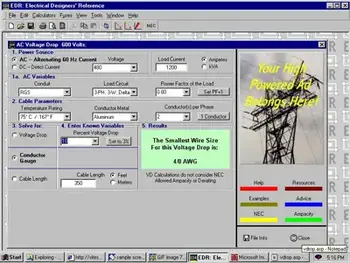
To use a VDC, you need to input the current flowing through the conductor, the length of the conductor, and the wire gauge or cable size. The tool then uses complex algorithms to calculate the VD in the circuit accurately. Based on the results, you can determine the appropriate wire size, cable length, and other specifications necessary to maintain an efficient and safe electrical system.


How is voltage drop calculated in a circuit?

VD is calculated in a circuit using Ohm's Law, which states that the VD across a conductor is equal to the product of the current and resistance. By knowing the current, resistance, and length of the conductor, you can calculate the VD and determine whether it falls within acceptable limits.


What factors affect voltage drop in a circuit?

The factors that affect VD in a circuit include the current flowing through the conductor, the length of the conductor, the resistance of the conductor, and the wire gauge or cable size. Other factors, such as the type of conductor and installation, can also affect VD.


Why is it important to calculate voltage drop?

Calculating VD is essential in maintaining an efficient and safe electrical system. VD can impact the performance of electrical equipment and devices, leading to hazards such as fires and electrical shock. By accurately calculating VD, engineers can select the appropriate wire size, cable length, and other necessary specifications to maintain an efficient and safe electrical system.


What are the benefits of using a VDC?

Using a VDC offers several benefits, including accurate calculations, time savings, cost reduction, and hazard prevention. By accurately calculating VD, engineers can select the appropriate wire size and other specifications, thereby reducing the cost of the electrical system. In addition, calculating VD accurately can prevent electrical hazards such as fires and shocks.


Are there any limitations to using a VDC?

While VDCs offer numerous benefits, they also have some limitations. For example, they rely on the accuracy of the input parameters, but may overlook other factors that can affect voltage drop, such as temperature and ambient conditions. Additionally, they may not be suitable for complex electrical systems.


What is the voltage drop per 100 ft?

The VD per 100 ft depends on various factors, including the current flowing through the conductor, the conductor's length, its resistance, and the wire gauge or cable size. Therefore, it is essential to calculate the VD accurately to determine the appropriate wire size and cable length necessary to maintain an efficient and safe electrical system.


What is a rule of thumb for voltage drop?

The rule of thumb for VD is that the VD in a circuit should not exceed 3% for power circuits and 5% for lighting circuits. These values are based on the National Electrical Code (NEC) guidelines, ensuring the electrical system operates efficiently and safely.

Southwire Voltage Drop Calculator


Related Pages


View more

What is Open Circuit Voltage? Explained

Open circuit voltage is the potential difference measured across the terminals of a device when no external load is applied. Common in batteries, solar cells, and electrical circuits, it helps evaluate performance, efficiency, and voltage characteristics.


What is Open Circuit Voltage?

It is the maximum voltage measured across terminals when no current flows in the circuit, providing a baseline for performance evaluation.

✅ Indicates battery and solar cell efficiency

✅ Helps assess electrical circuit performance

✅ Defines voltage without current flow

What is open circuit voltage? Often abbreviated as OCV, is an essential concept within electrical engineering, particularly relevant to professionals handling electrical systems or devices. Defined as the electrical potential difference between two points in a circuit when no current flows, OCV represents the maximum voltage achievable without applying a load. For electrical workers, understanding OCV is crucial, as it enables the evaluation of power sources and the identification of potential issues within a circuit before engaging with it under load. Knowledge of OCV benefits electrical workers by providing insights into system readiness, ensuring operational safety, and facilitating troubleshooting for optimal equipment performance. Understanding basic electricity is the foundation for grasping what open circuit voltage means, since it defines how voltage behaves when no current flows.


Determining Open Circuit Voltage

OCV can be measured using instruments like digital multimeters, which provide readings of the maximum electrical potential in the circuit. When conducting a test, it’s essential to measure the resistance between two terminals with no current flow. For instance, if a circuit is connected to a 12-volt battery with no load, the multimeter will display the OCV, which typically matches the battery’s maximum voltage. Similarly, in a solar cell, the OCV provides an indication of the maximum power it can generate when fully charged. Such measurements are helpful in evaluating the state of charge and operational status, providing valuable data to maintain system health. A solid grasp of electrical resistance is also critical, as resistance affects how potential differences are measured when a circuit is open.


Open Circuit Voltage Test

The open-circuit voltage test, also known as the no-load test, is a standard procedure in electrical engineering for assessing a power source's condition when it is not under load. In this test, an engineer connects a voltmeter to the terminals of a circuit to measure the OCV. This process is valuable for detecting issues such as short circuits, high resistance, or compromised wiring, which can lead to performance problems. The results from this test enable electrical professionals to detect weak points in a circuit before it operates under load, ensuring smoother and safer functionality. Open-circuit voltage is directly related to capacitance, as capacitors store electrical potential that can be measured under no-load conditions.


Applications of Open Circuit Voltage 

In practical applications, open circuit voltage is not just a measurement but a vital diagnostic tool. For example, in renewable energy systems, engineers often assess solar cell efficiency by examining its OCV. A solar cell’s OCV indicates its potential output, enabling accurate calculations of energy capacity and state of charge. Understanding OCV also aids in selecting voltage levels appropriate for different components, especially in high-voltage systems where matching component capacity is essential. In this way, OCV serves as a baseline for electrical potential, enabling engineers to optimize systems for both performance and safety. Engineers often compare OCV with direct current behavior, where stable voltages are easier to measure without the influence of alternating loads.

The concept of OCV has safety implications. By knowing the maximum potential voltage in a circuit before activating it, engineers can implement safeguards to avoid overloads or shorts that might occur under load. In electrical troubleshooting, measuring OCV allows for the identification of circuits that aren’t performing optimally, pinpointing faults or abnormal resistance that could lead to hazards. Hence, for electrical workers, mastering OCV measurement is not only about system performance but also about adhering to safety standards that protect both personnel and equipment.


Frequently Asked Questions


What is Open Circuit Voltage?

Open circuit voltage refers to the electrical potential, or maximum voltage, present between two conductors in a circuit when there is no active current flowing. This concept is applicable to both direct current (DC) and alternating current (AC) circuits. In DC systems, the OCV remains stable at a maximum level when no load is connected. In AC circuits, OCV may vary depending on factors such as load fluctuations and circuit design. The measurement of OCV is crucial for determining the performance of various devices, including solar cells, where the state of charge can be observed by checking the OCV. Electrical engineers and technicians can use this information to diagnose issues and assess the readiness of systems for operation. In 3-phase electricity systems, knowing the open circuit voltage helps engineers ensure balance and reliability before load conditions are applied.


Why Open Circuit Voltage Matters

For anyone working in electrical engineering, understanding open-circuit voltage is essential for designing and troubleshooting systems. OCV indicates the maximum voltage a circuit can sustain, helping engineers select compatible components and design for peak efficiency. For instance, when assessing a solar cell, the OCV helps identify the electrical potential it can generate without applying any load. In this way, OCV is a guide to the expected performance under load-free conditions, ensuring that devices will perform within specified limits when placed in actual operation. The concept also closely relates to active power, as OCV provides a baseline for calculating the amount of real power a system can deliver once current begins to flow.


Does open circuit voltage change with temperature?

Yes, temperature can affect open circuit voltage. For example, solar cells typically show a decrease in OCV as temperature rises, which impacts efficiency and energy output.


Is the open circuit voltage always equal to the source voltage?

Not always. While OCV often matches the nominal source voltage, internal resistance, aging, or chemical changes in a battery can cause the measured value to differ slightly.


Can open circuit voltage predict battery health?

OCV can give an indication of a battery’s state of charge, but it is not a complete measure of health. Additional tests, such as load testing, are needed to assess the overall condition.


How does open circuit voltage relate to safety testing?

Measuring OCV before energizing equipment enables engineers to confirm expected voltage levels and prevent hazardous conditions that may arise under load.


Is open circuit voltage used in AC systems as well as DC?

Yes, OCV applies to both AC and DC systems. In AC circuits, variations may occur depending on the design and frequency, whereas DC systems typically provide a stable maximum value.


What is open circuit voltage? Open circuit voltage is more than just a technical measurement; it is a vital reference point for understanding the behavior of batteries, solar cells, and electrical circuits under no-load conditions. By measuring OCV, electrical professionals gain valuable insights into efficiency, reliability, and safety before current flows, ensuring systems are prepared for real-world operation. Whether applied in renewable energy, troubleshooting, or equipment testing, open circuit voltage provides the foundation for sound engineering decisions and safer electrical practices.


Related Articles


View more

Sign Up for Electricity Forum’s Newsletter

Stay informed with our FREE Newsletter — get the latest news, breakthrough technologies, and expert insights, delivered straight to your inbox.

Electricity Today T&D Magazine Subscribe for FREE

Stay informed with the latest T&D policies and technologies.
  • Timely insights from industry experts
  • Practical solutions T&D engineers
  • Free access to every issue

Live Online & In-person Group Training

Advantages To Instructor-Led Training – Instructor-Led Course, Customized Training, Multiple Locations, Economical, CEU Credits, Course Discounts.

Request For Quotation

Whether you would prefer Live Online or In-Person instruction, our electrical training courses can be tailored to meet your company's specific requirements and delivered to your employees in one location or at various locations.