Electricity Prices Explained


Electricity Prices

Electricity prices reflect tariffs, kWh rates, time-of-use schedules, peak demand charges, and grid congestion, driven by generation costs, transmission losses, and load profiles in power systems and industrial electrical engineering.


What Are Electricity Prices?

Electricity prices are costs per kWh shaped by tariffs, time-of-use, demand charges, and grid operating constraints.

✅ Defined per kWh with time-of-use and demand charges

✅ Influenced by generation mix, transmission losses, congestion

✅ Managed via load control, demand response, smart metering


Electricity prices, or rates, are usually determined by electric utilities and the governmental organizations that oversee them. The fees an electric utility company charges its customers for service aer based on electricity prices set by government, except in the case where they cost electricity prices on a deregulated basis. In that case, electricity prices are determined by marketplace factors such as supply and demand. Electric utility companies charge their customers different rates, depending on the type of customer, the kind of contract, and on the customer's needs. Electricity Prices bill energy on the kwh basis of the individual customer's rate, the level of consumption, and other charges, such as taxes and fuel adjustments. This is how electricity billed. For a deeper breakdown of typical rate components, resources like electricity cost guides explain line items and surcharges clearly.

That collection of rates is called a tariff. The power tariff is designed to provide the privately owned electric utility with enough income to allow investors to earn a cash return and cover operation and maintenance costs. Most of the larger utilities operate as regulated franchises, meaning that the prices they charge are subject to public review, often by a State public utility commission. In competitive markets, customers may choose an electricity supplier while the utility still handles delivery services and billing oversight.

Publicly owned electric utilities are nonprofit, local government agencies established to provide service to their communities and nearby consumers at cost, returning excess funds to the consumer in the form of community contributions, more economic and efficient facilities, and lower power rates. To meet these community objectives, public power agencies plan their electricity supply over multiyear horizons to manage risk and affordability.

Publicly owned electric utilities (which number approximately 2,000) include municipals, public power districts, State authorities, irrigation districts, and other State organizations. Some of these organizations also own or contract for electricity generation assets to enhance self-sufficiency and rate stability.

There are approximately 900 cooperative electric utilities in the United States currently doing business in 47 States. These utilities are owned by their members and are established to provide power to those members. Because member education supports better usage decisions, many cooperatives provide primers on what electricity is and how it is measured on bills.

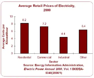
Average retail Electricity prices of power are calculated by dividing utility revenue by retail sales. The resulting measurement is the cost, or average revenue per kilowatthour, of power sold. (A kilowatthour is equal to one watt of power supplied to an electric circuit steadily for 1,000 hours.) Electric utilities usually offer three primary classes of service: residential, commercial, and industrial. The average price per kilowatthour for residential consumers is generally higher than for any other sector due in part to higher costs associated with serving many consumers who use relatively small amounts of power. In Ontario, the industrial sector has the lowest energy prices and energy bills rates every month due to the economies of serving a few consumers who use relatively large amounts of electricity. Understanding the distinction between energy in kilowatthours and instantaneous electricity power demand helps customers interpret peak charges and capacity fees. Regional consumption patterns, including trends in electricity demand in Canada, can influence wholesale prices and cross-border power flows affecting local rates.

Related News

Electricity Meter

An electricity meter measures electrical energy consumption in homes, businesses, and industries. Also called a power meter or energy meter, it records kilowatt-hours, supports billing, monitors usage patterns, and ensures accurate tracking of electrical load.


What is an Electricity Meter?

An electricity meter is a vital device that utility companies use to measure the amount of electric power consumed by a household or business.

✅ Tracks consumption in kilowatt-hours (kWh) for accurate billing

✅ Monitors load, efficiency, and usage trends over time

✅ Essential for power distribution, energy management, and safety


It provides valuable data that helps both consumers and utility companies monitor power consumption, leading to improved energy management and more accurate billing.


How does an electricity meter work?

It measures the amount of power a household or business consumes, typically in kilowatt-hours (kWh). It records usage over time, allowing utility companies to bill customers accordingly.

Various types exist to suit different applications. The most common include:

  • Electromechanical meters (kWh) with a rotating aluminum disc that measures energy flow.

  • Digital meters that display consumption on an electronic screen.

  • Smart meters are advanced digital devices that automatically transmit usage data to the utility.

Smart meters are central to the smart grid, a modernized system designed to improve the efficiency and reliability of power distribution. With a smart device, consumers can access real-time information about their usage while utilities can implement time-of-use billing to encourage energy conservation during peak hours.


Net Metering & Solar Export Meters

For households with solar panels or other distributed energy sources, net recorders facilitate two-way power flow. They measure both the electrical energy consumed from the grid and the power exported back to it. This enables net metering programs, allowing consumers to earn credits or payments for surplus energy, making the adoption of renewable energy more cost-effective.


Communication & Technology Behind Smart Meters

Smart meters are part of the Advanced Metering Infrastructure (AMI), which utilizes communication networks, including RF mesh, cellular, and power line communication (PLC), to securely transmit usage data to the utility. This connectivity enables demand response programs, remote disconnections, and predictive maintenance, while providing consumers with detailed insights via apps and dashboards.


How do I read my Electricity Meter?

Reading your device may seem complicated, but it’s straightforward:

  • Electromechanical types use dials. Read each from left to right, taking the lower number if the pointer is between two digits.

  • Digital types display readings directly on an LCD screen, often cycling through consumption, demand, and tariff data.
    Some utilities also offer web portals or mobile apps that allow consumers to track their daily or hourly usage.


How can I check if my Electricity Meter is accurate?

To test accuracy, turn off all appliances and observe whether the recorder continues to record consumption. If it does, contact your utility for a professional inspection. Most utilities are required by regulation to maintain meter accuracy within specific tolerances defined by ANSI or IEC standards.

One innovation is the prepaid electricity meter, where consumers pay in advance for power. Once the credit is exhausted, the supply is disconnected until it is recharged. This approach enables households to budget more effectively and promotes conscious energy use.


Security & Privacy in Modern Meters

Electricity meter tampering is a significant concern for utilities. Attempts to reduce recorded consumption can lead to safety hazards and financial losses. Modern recorders include anti-tamper seals, encrypted communication, and intrusion detection to protect data integrity and ensure accurate billing. Utilities also conduct regular inspections to detect and prevent fraud.


What is a Smart Electricity Meter, and how does it differ?

It is a digital device that provides real-time usage data, supports two-way communication, and integrates with the smart grid. Unlike traditional recorders, it enables:

  • Automated reading

  • Dynamic tariffs and demand response

  • Access to consumer dashboards, apps, and alerts

These capabilities enhance billing accuracy, empower consumers to lower their energy costs, and facilitate a more flexible and sustainable grid.


Market Adoption & Trends

Smart meter adoption is growing worldwide. According to industry reports, over 1 billion smart meters have been deployed globally, with continued growth expected in North America, Europe, and Asia. In Canada, utilities like BC Hydro have rolled out smart meters to millions of customers, aiming for more reliable service and reduced outages.


Pros, Cons, and Challenges

Electricity meters offer several clear benefits, including accurate billing, improved energy management, integration with renewable energy sources, and reduced costs associated with manual meter reading. However, challenges include upfront costs, connectivity issues, consumer privacy concerns, and potential inaccuracies if meters drift out of calibration. Addressing these ensures the technology continues to deliver long-term benefits.


The Role of Electricity Meters in Energy Management

Understanding how they work, how to read them, and the different types available helps consumers make informed decisions about their energy usage. By verifying accuracy, adopting advanced technologies such as smart and prepaid meters, and utilizing apps and dashboards, households and businesses can gain greater control over their energy costs.

Ultimately, electricity meters are not just billing devices—they are gateways to improved efficiency, consumer empowerment, and a sustainable energy future.


Frequently Asked Questions


Can I read my smart meter remotely?

Yes. Most enable consumers to view their data via apps or online dashboards provided by their utilities.


How accurate are they?

They must comply with standards like ANSI C12 or IEC 62053, ensuring accuracy within strict tolerances.


What happens if it fails?

If it malfunctions, utilities are legally required to replace it and may use historical usage patterns for interim billing.


Related Articles


View more

Electricity Grid - T&D

Electricity grid infrastructure delivers power through transmission lines, substations, and smart grid controls, balancing voltage and frequency, integrating renewable energy, enabling demand response, improving reliability, and supporting utilities with real-time monitoring and load management.


What Is the Electricity Grid?

A network of transmission, distribution, and control systems that delivers reliable electrical power to consumers.

✅ Transmits high-voltage power from plants to local networks

✅ Steps down voltage at substations for safe distribution

✅ Integrates renewables with smart grid and demand response


The electricity grid is a complex and essential component of modern society. It provides the power necessary to operate homes, businesses, and industries, and it is constantly evolving to meet the demands of a changing world. From power generation to distribution, transmission lines to load balancing and renewable energy integration, every component is critical in ensuring we can access reliable and affordable energy whenever needed. For a broader primer, resources such as electric power systems outline how these elements interconnect in practice.

At its core, the grid is a system that connects power generation facilities to consumers through transmission lines and distribution systems. It is designed to move electricity from where it is generated to where it is needed, whether in a residential home or a large industrial facility. The term "grid" refers to the interconnectedness of these systems, which allows power to flow from one location to another as needed. The federal energy regulatory commission ferc regulates the grid.

In North America, the transmission and distribution (T&D) grid is managed by federal, state, provincial, and territorial agencies. The grid is divided into various regions, each with its grid operator responsible for ensuring reliable and efficient operation within their respective jurisdiction. For instance, Canada's power delivery network is divided into four main regions: Western Canada, Ontario, Quebec, and the Atlantic region. Similarly, the United States' electricity grid is divided into three major interconnected systems: the Eastern Interconnection, Western Interconnection, and the Electric Reliability Council of Texas (ERCOT) system. Each region's grid operator works closely with neighbouring grid operators to ensure a seamless flow of electrical power across the interconnected grid, even during periods of high demand or unexpected outages.

The power delivery network can be broken down into three main components: power generation, transmission, and distribution. Power generation facilities can take many forms, including coal-fired, natural gas, nuclear, and renewable energy sources such as wind and solar. These facilities generate electrical power transmitted over high-voltage transmission lines to substations, where the voltage is lowered for distribution to homes and businesses through a network of distribution lines. For those new to supply technologies, overviews of how electricity is generated cover conventional and renewable pathways.

Transmission lines are a critical component of the T&D system, which deliver and produce electricity at higher voltages. T&D provides the means to move large amounts of electrical power over long distances. These lines are typically made of high-strength steel or aluminum and span hundreds of miles. They are also designed to be highly resilient to extreme weather events such as hurricanes, tornadoes, and ice storms. Understanding ratings, capacity, and losses draws on electricity power fundamentals that inform planning and operations.

The distribution system is the final component of the power grid, responsible for delivering electrical power directly to homes and businesses. This system includes transformers, power lines, and meters, which work together to regulate power flow to individual consumers. The distribution system also includes local power generation facilities, such as rooftop solar panels and small-scale wind turbines, which can supplement the power provided by the grid. To see how fuel mixes influence local grids, summaries of sources of electricity highlight regional differences.

As the world increasingly relies on electrical power, there is a growing need to modernize and upgrade the power delivery network to meet the demands of the 21st century. One approach to this is the development of a smart grid, which uses advanced sensors, communication networks, and analytics to optimize the flow of power and improve reliability. Another approach is the integration of renewable energy sources such as wind and solar into the grid, which can reduce greenhouse gas emissions and improve grid resilience. Advanced planning and forecasting increasingly leverage power system analysis to evaluate contingencies and optimize investments.

Load balancing is another critical function, ensuring that real-time power generation and consumption are matched. This is accomplished through a combination of forecasting, automated control systems, and energy storage facilities such as batteries and pumped hydroelectric storage. In flexible markets, insights into electricity generation help operators schedule resources effectively.

Reliability and resilience are also crucial factors in its overall performance. The grid must be designed to withstand extreme weather events and other disruptions, such as cyberattacks or equipment failures. This requires a combination of robust engineering and effective emergency response planning.


What is an electricity grid, and how does it work?

A T&D system is a complex network of power generation facilities, transmission lines, and distribution systems that work together to ensure reliable and affordable energy is available to consumers. At its core, the grid is a system that connects power generation facilities to consumers through transmission lines and distribution systems. It is designed to move electrical power from where it is generated to where it is needed, whether in a residential home or a large industrial facility. The grid uses high-voltage transmission lines to move electrical power over long distances, then lowers the voltage through transformers for distribution to homes and businesses. For foundational clarity, a concise explainer on what electricity is helps connect basic concepts to grid operations.


What is the difference between the transmission and distribution systems?

The transmission system is responsible for moving large amounts of electrical power over long distances at high voltages. This is accomplished through a network of high-voltage transmission lines and substations spanning hundreds of miles. The distribution system delivers electrical power directly to homes and businesses at lower voltages. This system includes transformers, power lines, and meters, which work together to regulate the flow of electricity to individual consumers.


How is renewable energy integrated?

Renewable energy sources such as wind and solar are integrated into the T&D system through a process called interconnection. This involves connecting the renewable energy source to the grid through a substation and transformer, ensuring that the energy generated can be transmitted to consumers. Renewable energy sources can also be connected to the grid through distributed generation, where energy is generated on-site at the point of consumption, such as through rooftop solar panels.


What are the challenges associated with maintaining the reliability and resilience of the T&D system?

Maintaining reliability and resilience is a complex task requiring robust engineering and effective emergency response planning. Some of the challenges associated with this include extreme weather events, cyberattacks, equipment failures, and natural disasters. In addition, as the grid becomes more reliant on renewable energy sources, new challenges may arise related to load balancing and energy storage.


What is a smart grid, and how does it differ from a traditional T&D system?

A smart grid is a modernized version of the traditional T&D system that uses advanced sensors, communication networks, and analytics to optimize the flow of electrical power and improve reliability. Unlike a traditional T&D system, designed to move electrical power from power plants to consumers, a smart grid enables two-way communication between consumers and the grid. This allows for greater control and flexibility in managing energy usage and improved efficiency and reliability.


How can energy storage be used to support the T&D system?

Energy storage can be used to support the T&D system in several ways. One essential function is to provide backup power in the event of a blackout or other disruption to the grid. Energy storage can also help balance the load on the grid, ensuring that power generation and consumption are matched in real-time. In addition, energy storage can help integrate renewable energy sources into the grid by storing excess energy for use during times of low generation.


What is grid modernization, and why is it important for the future of the T&D system?

Grid modernization refers to upgrading and improving the T&D system to meet the demands of a changing world. This may involve the development of a smart grid, the integration of renewable energy sources, and the deployment of advanced sensors and control systems. Grid modernization is important for the future of the T&D system because it will enable greater efficiency, reliability, and sustainability while ensuring that the grid is resilient to emerging threats and challenges.


Related Articles

View more

Electrical Resistance Definition Explained

Electrical resistance definition explains how materials oppose current flow in circuits, measured in ohms, linked to voltage, resistivity, conductor geometry, temperature, and impedance, governed by Ohm's law and SI units in electronics.


What Is Electrical Resistance Definition?

It is the measure of how a material opposes electric current, equal to voltage divided by current and measured in ohms.

✅ Measured in ohms; per Ohm's law, resistance R equals voltage V over current I.

✅ Depends on material resistivity, length, cross-sectional area, and temperature.

✅ Key in circuit analysis, power dissipation, signal integrity, and safety.


Electrical Resistance Definition: ER occurs in an electrical circuit when current-carrying charged particles collide with fixed particles that make up the structure of the conductors. Resistance is measured in ohm. Resistance is the ohm w. Resistance occurs in every part of a circuit, including wires and especially power transmission lines. For a concise overview, see this introduction to electrical resistance to reinforce key definitions.

Dissipation of electric energy in the form of heat affects the amount of driving voltage required to produce a given current through the circuit. In fact, volts are mesured across a circuit divided by the current I (amperes) through that circuit defines quantitatively the amount of electrical resistance R. The ohm is the common unit of electrical resistance, equivalent to one volt per ampere and represented by the capital Greek letter omega, Ω. The electrical resistance of a wire is directly proportional to its length and inversely proportional to its cross-sectional area. Resistance also depends on the material of the conductor. For instance, the resistance of a conductor generally increases with increasing temperature the resistivity. This is why some conductors have almost zero resistance when cooled to extremely low temperatures, as is the case with superconductors, because of the relative resistivity of metals. There is a temperature coefficient of resistivity. If you need a refresher on potential difference and its role in circuits, review this explanation of voltage to connect the concepts.

Alternating-current resistors for current measurement require further design consideration. For example, if the resistor is to be used for current-transformer calibration, its ac resistance must be identical with its dc resistance within 1/100th% or better, and the applied voltage difference between its voltage terminals must be in phase with the current through it within a few tenths of a minute. Thin strips or tubes of resistance material are used to limit eddy currents and minimize "skin" effect, the current circuit must be arranged to have small self-inductance, and the leads from the voltage taps to the potential terminals should be arranged so that, as nearly as possible, the mutual inductance between the voltage and current circuits opposes and cancels the effect of the self-inductance of the current circuit. In (a) a metal strip has been folded into a very narrow U; in (b) the current circuit consists of coaxial tubes soldered together at one end to terminal blocks at the other end; in (c) a straight tube is used as the current circuit, and the potential leads are snugly fitting coaxial tubes soldered to the resistor tube at the desired separation and terminating at the center. These design choices are also easier to contextualize by comparing common types of resistors used for precise AC measurements.

Electrical Resistance coils consist of insulated resistance copper wire wound on a bobbin or winding form, hard-soldered at the ends to copper terminal wires. Metal tubes are widely used as winding form for dc resistors because they dissipate heat more readily than insulating bobbins, but if the resistor is to be used in ac measurements, a ceramic winding form is greatly to be preferred because it contributes less to the phase-defect angle of the resistor. The resistance wire ordinarily is folded into a narrow loop and wound bifilar onto the form to minimize inductance. This construction results in considerable associated capacitance of high-resistance coils, for which the wire is quite long, and an alternative construction is to wind the coil inductively on a thin mica or plastic card. The capacitive effect is greatly reduced, and the inductance is still quite small if the card is thin. When specifying coil assemblies, it helps to recall the standardized unit of electrical resistance so ratings and tolerances are interpreted consistently.

Resistors in which the wire forms the warp of a woven ribbon have lower time constants than either the simple bifilar- or card-wound types. Manganin is the resistance material most generally employed, but Evanohm and similar alloys are beginning to be extensively used for very high resistance coils. Enamel or silk is used to insulate the wire, and the finished coil is ordinarily coated with shellac or varnish to protect the wire from the atmosphere. Such coatings do not completely exclude moisture, and dimensional changes of insulation with humidity will result in small resistance changes, particularly in high resistances where fine wire is used. Material behavior, moisture effects, and long term stability are discussed further in this broader overview of electrical resistance for additional context.

Electrical Resistance boxes usually have two to four decades of resistance so that with reasonable precision they cover a considerable range of resistance, adjustable in small steps. For convenience of connection, terminals of the individual resistors are brought to copper blocks or studs, which are connected into the circuit by means of plugs or of dial switches using rotary laminated brushes; clean, well-fitted plugs probably have lower resistance than dial switches but are much less convenient to use. The residual inductance of decade groups of coils due to switch wiring, and the capacitance of connected but inactive coils, will probably exceed the residuals of the coils themselves, and it is to be expected that the time constant of an assembly of coils in a decade box will be considerably greater than that of the individual coils. Understanding how series and parallel combinations set the equivalent resistance will inform how decade boxes are deployed in complex networks.

Measurement of resistance is accomplished by a variety of methods, depending on the magnitude of the resistor and the accuracy required. Over the range from a few ohms to a megohm or more, an ohmmeter may be used for an accuracy of a few percent. A simple ohmmeter may consist of a milliammeter, dry cell, and resistor in a series circuit, the instrument scale being marked in resistance units, if you obey ohm law. For a better value, the voltage drop is measured across the resistor for a measured or known current through it. Here, accuracy is limited by the instrument scales unless a potentiometer is used for the current and voltage measurements. The approach is also taken in the wide variety of digital multimeters now in common use. Their manufacturers' specifications indicate a range of accuracies from a few percent to 10 ppm (0.001%) or better from the simplest to the most precise meters. Bridge methods can have the highest accuracy, both because they are null methods in which two or more ratios can be brought to equality and because the measurements can be made by comparison with accurately known standards. For two-terminal resistors, a Wheatstone bridge can be used; for four-terminal measurements, a Kelvin bridge or a current comparator bridge can be used. Bridges for either two- or four-terminal measurements also may be based on resistive dividers. Because of their extremely high input impedance, digital voltmeters that be used with standard resistors in unbalanced bridge circuits of high accuracy. For quick reference during test planning, the fundamental resistance formula clarifies how R, V, and I are related under Ohm law.

Digital multi meters are frequently used to make low-power measurements of resistors in the range between a few ohms and a hundred megohms or so. Resolution of such instruments varies from 1% of full scale to a part per million of full scale. These meters generally use a constant-current source with a known current controlled by comparing the voltage drop on an internal "standard" resistor to the EMF produced by a Zener diode. The current is set at such a level as to make the meter direct-reading in terms of the displayed voltage; that is, the number displayed by the meter reflects the voltage drop across the resistor, but the decimal point is moved and the scale descriptor is displayed as appropriate. Multimeters typically use three or more fixed currents and several voltage ranges to produce seven or more decade ranges with the full-scale reading from 1.4 to 3.9 times the range. For example, on the 1000-0 range, full scale may be 3,999.999 Q. Power dissipated in the measured resistor generally does not exceed 30 mW and reaches that level only in the lowest ranges where resistors are usually designed to handle many times that power. The most accurate multimeters have a resolution of 1 to 10 ppm of range on all ranges above the 10-0 range. Their sensitivity, linearity, and short-term stability make it possible to compare nominally equal resistors by substitution with an uncertainty 2 to 3 times the least count of the meter. This permits their use in making very accurate measurements, up to 10 ppm, or resistors whose values are close to those of standards at hand. Many less expensive multimeters have only two leads or terminals to use to make measurements. In those cases, the leads from the meter to the resistor to be measured become part of the measured


Related Articles

View more

Lenz's Law Explained

Lenz’s Law is a principle of electromagnetic induction stating that induced current flows in a direction that opposes the change in magnetic flux producing it. This rule ensures energy conservation and explains how circuits, coils, generators, and transformers behave in changing fields.


What is Lenz’s Law?

Lenz’s Law, rooted in Faraday’s Law of Induction, states that the direction of an induced current or electromotive force (emf) always opposes the change in magnetic flux that produced it. This principle safeguards conservation of energy in electromagnetic systems.

✅ Explains opposing force in induced current and magnetic fields

✅ Fundamental to understanding circuits, transformers, and generators

✅ Practical in energy conversion, electric motors, and induction device

Lenz's Law, named after the Russian physicist Heinrich Lenz (1804-1865), is a fundamental principle in electromagnetism. It states that the direction of the induced electromotive force (emf) in a closed conducting loop always opposes the change in magnetic flux that caused it. This means that the induced current creates a magnetic field that opposes the initial change in magnetic flux, following the principles of conservation of energy. A strong grounding in basic electricity concepts makes it easier to see why Lenz’s Law is central to modern circuit design.


Understanding Lenz's Law enables us to appreciate the science behind various everyday applications, including electric generators, motors, inductors, and transformers. By exploring the principles of Lenz's Law, we gain insight into the inner workings of the electromagnetic world that surrounds us. Engineers use this principle when designing three-phase electricity systems and 3-phase power networks to maintain energy balance.

Lenz's Law, named after the Russian physicist Heinrich Lenz (1804-1865), is a fundamental principle that governs electromagnetic induction. It states that the induced electromotive force (emf) in a closed conducting loop always opposes the change in magnetic flux that caused it. In simpler terms, the direction of the induced current creates a magnetic field that opposes the initial change in magnetic flux. 

Lenz's Law is a fundamental law of electromagnetism that states that the direction of an induced electromotive force (EMF) in a circuit is always such that it opposes the change that produced it. Mathematically, Lenz's Law can be expressed as:

EMF = -dΦ/dt

Where EMF is the electromotive force, Φ is the magnetic flux, and dt is the change in time. The negative sign in the equation indicates that the induced EMF is in the opposite direction to the change in flux.

Lenz's Law is closely related to Faraday's Law of electromagnetic induction, which states that a changing magnetic field induces an EMF in a circuit. Faraday's Law can be expressed mathematically as:

EMF = -dΦ/dt

where EMF is the electromotive force, Φ is the magnetic flux, and dt is the change in time.

Ampere's Law and the Biot-Savart Law are also related to Lenz's Law, as they describe the behaviour of electric and magnetic fields in the presence of currents and charges. Ampere's Law states that the magnetic field around a current-carrying wire is proportional to the current and the distance from the wire. The Biot-Savart Law describes the magnetic field produced by a current-carrying wire or a group of wires. Because Lenz’s Law governs the behavior of induced currents, it directly complements Ampere’s Law and the Biot-Savart Law in explaining magnetic fields.

Together, these laws provide a complete description of the behaviour of electric and magnetic fields in various situations. As a result, they are essential for understanding the operation of electric motors, generators, transformers, and other devices.

To better understand Lenz's Law, consider the scenario of a bar magnet moving toward a coil of wire. When the magnet moves closer to the coil, the number of magnetic field lines passing through the coil increases. According to Lenz's Law, the polarity of the induced emf in the coil is such that it opposes the increase in magnetic flux. This opposition creates an induced field that opposes the magnet's motion, ultimately slowing it down. Similarly, when the magnet is moved away from the coil, the induced emf opposes the decrease in magnetic flux, creating an induced field that tries to keep the magnet in place.

The induced field that opposes the change in magnetic flux follows the right-hand rule. If we hold our right hand around the coil such that our fingers point in the direction of the magnetic field lines, our thumb will point in the direction of the induced current. The direction of the induced current is such that it creates a magnetic field that opposes the change in the magnetic flux.

The pole of the magnet also plays a crucial role in Lenz's Law. When the magnet's north pole moves towards the coil, the induced current creates a magnetic field that opposes the north pole's approach. Conversely, when the magnet's south pole moves towards the coil, the induced current creates a magnetic field that opposes the south pole's approach. The direction of the induced current follows the right-hand rule, as we discussed earlier.

It is related to Faraday's Law of Electromagnetic Induction, which explains how a changing magnetic field can induce an electromotive force (emf) in a conductor. Faraday's Law mathematically describes the relationship between the induced electromotive force (emf) and the rate of change of magnetic flux. It follows Faraday's Law, as it governs the direction of the induced emf in response to the changing magnetic flux. To fully understand how electromagnetic induction works, it is helpful to see how Faraday’s discoveries laid the foundation for Lenz’s Law.

It is also related to the phenomenon of eddy currents. Eddy currents are loops of electric current induced within conductors by a changing magnetic field. The circulating flow of these currents generates their magnetic field, which opposes the initial magnetic field that created them. This effect is in line with Lenz's Law and has practical applications, such as in the braking systems of trains and induction cooktops.

Lenz's Law has numerous practical applications in our daily lives. For example, it plays a significant role in the design and function of electric generators, which convert mechanical energy into electrical energy. In a generator, a rotating coil experiences a changing magnetic field, resulting in the generation of an electromotive force (emf). The direction of this induced emf is determined by Lenz's Law, which ensures that the system conserves energy. Similarly, electric motors operate based on Lenz's Law. In an electric motor, the interaction between the magnetic fields and the induced electromotive force (emf) creates a torque that drives the motor. In transformers, including 3-phase padmounted transformers, Lenz’s Law explains why flux changes are controlled for efficiency and safety.

Lenz's Law is an essential concept in the design of inductors and transformers. Inductors are electronic components that store energy in their magnetic field when a current flows through them. They oppose any change in the current, following the principles of Lenz's Law. Transformers, which are used to transfer electrical energy between circuits, utilize the phenomenon of electromagnetic induction. By understanding it, engineers can design transformers.


Related Articles


View more

Capacitance in Series

Capacitance in series reduces overall capacitance by summing the reciprocals of each capacitor. This concept is essential in electronics, circuit analysis, and power systems, ensuring proper charge storage, voltage division, and reliable circuit performance.


What is Capacitance in Series?

When capacitors are connected in series, their combined behavior follows specific rules that affect voltage distribution, total capacitance, and charge consistency.

✅ Reduces total capacitance as capacitors share the voltage

✅ Total capacitance is calculated using the reciprocal formula

✅ Charge on each capacitor is equal in a series circuit


In a series circuit, connecting more than one capacitor in series affects how voltage and charge are distributed, directly impacting the total capacitance of the system. Unlike parallel arrangements, a series setup reduces the overall capacitance and requires the use of a reciprocal formula to calculate the correct value. This configuration functions like a voltage divider, where the total voltage is split across each capacitor based on its individual capacitance. While this reduces the system’s ability to store charge, it also controls how voltage is allocated, which is useful in applications where precise energy storage and voltage regulation are needed.

For a clearer technical explanation, see our what is capacitance page, which breaks down how this key property affects circuit design.

When working with individual capacitors in electronic circuits, it is essential to understand their behaviour and effects. For example, in a series arrangement, the positive plate of one capacitor is connected to the negative plate of the next capacitor in line. This unique connection affects the circuit's total equivalent capacitance (C_total), resulting in a total capacitance that is smaller than the smallest individual capacitance (C) present in the series. The total capacitance of capacitors in series is always less than the value of the smallest individual capacitor in the arrangement.

A series circuit is characterized by its linear sequence of components, through which the current flows in a single path. In such circuits, the total voltage is distributed across each component in proportion to its resistance. The overall resistance of a series circuit is equal to the sum of the individual resistances of the connected components. The unit of capacitance, the farad, measures a capacitor’s ability to store electric charge per unit voltage.

When they are connected in series, the total C of the circuit is affected. This is because the positive plate of the capacitors is connected in series to the total C. Each capacitor stores the same charge in this arrangement, and the total voltage is divided across the capacitors in proportion to their C. This characteristic of series-connected capacitors plays a significant role in designing electronic circuits that require specific voltage and charge distribution properties. To fully grasp how capacitors behave in series, it’s important to understand what is a capacitor and how it stores and releases electrical energy.


Capacitors in Series: Formula, Voltage, and Charge Characteristics

Feature Capacitors in Series
Total Capacitance Less than the smallest individual capacitor
Formula 1/Ctotal = 1/C₁ + 1/C₂ + 1/C₃ + ...
Voltage Distribution Voltage divides across capacitors based on capacitance values
Charge on Capacitors Same charge on all capacitors
Use Case Used when reduced overall capacitance is needed in a circuit
Energy Storage Lower total energy storage than a single capacitor with same voltage


Different types of capacitors, such as ceramic or electrolytic, behave differently in series configurations based on their construction and rated voltage.


Formula for Calculation

To accurately calculate the total C of capacitors connected in series, the following formula is employed:

C_total = 1 / (1/C1 + 1/C2 + 1/C3 + ... + 1/Cn)

This formula calculates the inverse of the total C. To find the actual total C, take the inverse of the sum of the inverse individual capacitances. This mathematical process enables the precise determination of the overall capacitance value in a series configuration, which is crucial when designing or analyzing electronic circuits.


Impact of the Smallest Capacitor on Total Capacitance

When several are connected in series, the total C becomes smaller than the smallest individual C. This phenomenon occurs because the capacitor with a smaller capacitance (C) limits the total capacitance (C), acting as a bottleneck for current flow and restricting the total charge stored in the circuit. Understanding this limiting effect is critical when selecting capacitors for a series configuration, as the smallest capacitor will significantly impact the overall performance of the electronic circuit. Engineers must also consider electrical resistance, which affects how current and voltage behave in conjunction with capacitors in mixed-component circuits.


Comparing Capacitors in Parallel and Series Configurations

In contrast to capacitors in series, when capacitors are connected in parallel, the total C is the sum of the individual capacitances. This difference occurs because each capacitor is directly connected to the power source in a parallel circuit, allowing it to store its charge independently. Consequently, capacitors in parallel configurations offer higher overall capacitance values, making them suitable for applications that require increased charge storage capabilities. Reviewing electrical resistance definition can help clarify how resistance and C work together in impedance-sensitive designs. You can explore how capacitance in parallel differs from series configurations when designing circuits requiring larger energy storage.


Equivalent Capacitance and Voltage Drop in Series Capacitors

The equivalent C of capacitors connected in series can be determined by dividing the total charge stored in the circuit by the total voltage across the circuit. This is because the total charge stored in the circuit equals the sum of the charges on each capacitor. In contrast, the total voltage is calculated to determine the total capacitance for the number of capacitors connected.

The voltage drop in capacitors connected in series is divided among the capacitors in proportion to their C. This means that the voltage across each capacitor is proportional to its C. Understanding the voltage drop distribution in series capacitors is essential when designing circuits that rely on specific voltage levels across components.


Replacing Capacitors in Series with a Single Equivalent Capacitor and Combination Circuits

In some cases, capacitors in series can be replaced with a single equivalent capacitor that has the same C value as the equivalent capacitance of the series capacitors. This replacement technique can simplify circuit design and analysis, consolidating multiple components into a single element with equivalent electrical properties.

In a combination circuit, capacitors are connected in both series and parallel configurations. These complex arrangements are commonly found in practical electronic applications, as they offer more flexibility and adaptability in achieving desired circuit properties. To calculate the total C of a combination circuit, first, compute the capacitance of each series combination, then add those capacitances to find the total C. This process may involve several steps, as the designer needs to consider the contributions of both series and parallel components to the overall C value.


Applications and Considerations of Capacitors in Series

Capacitors in series configurations are utilized in various electronic applications, such as power supply filtering, signal coupling, and decoupling, as well as in tuning and timing circuits. When designing these applications, engineers must consider the capacitors' voltage ratings, tolerances, temperature coefficients, and other parameters to ensure the circuit functions as desired.

One crucial consideration when working with capacitors in series is the voltage rating. The voltage rating of each capacitor must be sufficient to handle the voltage that will be applied across it. Since the total voltage is distributed among the capacitors in series, selecting capacitors with appropriate voltage ratings is essential to prevent component failure or degradation.

Another important consideration is the capacitors' tolerances, which indicate the possible variation in C values from their nominal specifications. Capacitors with tighter tolerances may be required for precise applications, as variations in C values can impact the overall performance of the electronic circuit. 


Related Articles


View more

Tidal Electricity From Wave Action

Tidal electricity converts predictable ocean tides into renewable energy using tidal turbines, barrages, and lagoons, delivering stable baseload marine power, efficient grid integration, low carbon emissions, and robust reliability through advanced hydrodynamics and power electronics.


What Is Tidal Electricity?

Tidal electricity generates grid power from ocean tides via turbines or barrages, providing predictable, low-carbon output.

✅ Uses tidal stream turbines, barrages, and lagoons

✅ Predictable output enhances grid stability and capacity planning

✅ Power electronics enable efficient conversion and grid integration


Tidal electricity is obtained by utilizing the recurring rise and fall of coastal waters. Marginal marine basins are enclosed with dams, making it possible to create differences in the water level between the ocean and the basins. The oscillatory flow of water filling or emptying the basins is used to drive hydraulic turbines which propel wave generators. As a specialized branch of hydroelectricity, tidal schemes convert predictable water level differences into dispatchable power.

The cyclical movement of seawater exemplifies how water electricity systems depend on fluid dynamics and site geometry.

Large amounts of wave generation could be developed in the world's coastal regions having tides of sufficient range, although even if fully developed this would amount to only a small percentage of the world's potential hydroelectric power. In global electricity production portfolios, tidal energy typically plays a niche role alongside other renewables.

Because installations are coastal and infrastructure-intensive, they can contribute to regional green electricity targets with long service lives.

It is produced by turbines operated by tidal flow. Many ideas for harnessing the tides were put forward in the first half of the 20th century, but no scheme proved technically and economically feasible until the development by French engineers of the plan for the Rance power plant in the Gulf of Saint-Malo, Brittany, built 1961–67. A dam equipped with reversible turbines (a series of fixed and moving blades, the latter of which are rotated) permits the tidal flow to work in both directions, from the sea to the tidal basin on the flood and on the ebb from the basin to the sea. The Rance plant has 24 power units of 10,000 kilowatts each; about seven-eighths of the power is produced on the more controllable ebb flow. The sluices fill the basin while the tide is coming in and are closed at high tide. Emptying does not begin until the ebb tide has left enough depth of fall to operate the turbines. Conversely, the turbines are worked by the incoming tide to the basin. With reversible bulb turbines, both ebb and flood flows generate electricity with high capacity factors during spring tides.

Compared with windmills for electricity, tidal turbines benefit from dense water flow that yields steadier torque.

The Soviet Union completed construction in 1969 of a plant of about 1,000 kilowatts on the White Sea. Other sites of interest for tidal power plants include the Bay of Fundy in Canada, where the tidal range reaches more than 15 m (49 feet). Although large amounts of power are available from the tides in favourable locations, this power is intermittent and varies with the seasons. Grid planners often pair tidal plants with storage and flexible resources used in electricity windmill operations to smooth variability.


Related Articles

View more

Sign Up for Electricity Forum’s Newsletter

Stay informed with our FREE Newsletter — get the latest news, breakthrough technologies, and expert insights, delivered straight to your inbox.

Electricity Today T&D Magazine Subscribe for FREE

Stay informed with the latest T&D policies and technologies.
  • Timely insights from industry experts
  • Practical solutions T&D engineers
  • Free access to every issue

Live Online & In-person Group Training

Advantages To Instructor-Led Training – Instructor-Led Course, Customized Training, Multiple Locations, Economical, CEU Credits, Course Discounts.

Request For Quotation

Whether you would prefer Live Online or In-Person instruction, our electrical training courses can be tailored to meet your company's specific requirements and delivered to your employees in one location or at various locations.